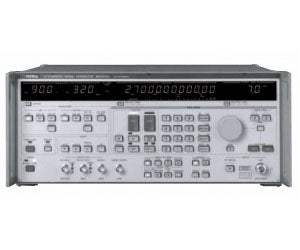
The MG3633A is a synthesized signal generator covering 10 kHz to 2700 MHz. It combines fine frequency resolution, fast frequency switching speed, high signal purity, and a high output level with amplitude, frequency, and phase modulation functions. Sweep functions for carrier frequency, output level, and modulation frequency let the instrument exercise a wide variety of devices under test, while onboard memory retains a large set of carrier frequencies and a library of panel settings.
A synthesized signal generator produces a precise, stable carrier whose frequency, level, and modulation can be set and swept under tight control, providing the known stimulus that receiver and component measurements depend on. The MG3633A is suited to research and development of mobile communications in the quasi-microwave band, along with performance evaluation, characteristics testing, and adjustment of radio equipment such as digital land-based mobile communications, mobile satellite communications, satellite broadcasting, and radio LANs. Its spectral purity also makes it useful for testing radio receiver selectivity, generating high-speed clocks for A/D converters and dividers, and producing standard signals for communications links.
ValueTronics stocks and holds its own inventory in a 20,000 square foot secure warehouse at 1675 Cambridge Drive in Elgin, Illinois, so the instruments we sell sit on our own shelves rather than being sourced on demand. Every used unit is inspected and functionally verified in house before it ships, while new units leave the factory seal intact exactly as received, giving buyers a consistent, verified source for both new and pre-owned test equipment.
| Specification | Value |
|---|---|
| Carrier Frequency | |
| Range | 10 kHz to 2700 MHz |
| Resolution | 0.01 Hz |
| Accuracy | Same as that of the reference oscillator |
| Internal reference oscillator | Frequency: 10 MHz. Start-up characteristics: after 30 minutes of operation ≤1 x 10⁻⁷/day, after 60 minutes of operation ≤5 x 10⁻⁸/day. Aging rate: after 24 hours of operation ≤2 x 10⁻⁸/day. Temperature characteristics: ±5 x 10⁻⁸/day (0° to 50°C) |
| External reference signal input | 10 MHz, TTL Level, BNC connector on rear panel |
| Reference signal output | 10 MHz, TTL Level, BNC connector on rear panel |
| Switching time | ≤10 ms (time from last command until frequency has stabilized to within ±500 Hz of set frequency, during remote operation) |
| Output | |
| Range | –143 to +23 dBm |
| Units | dBm, dBµV, V, mV, µV (Terminated and open voltages are selectable for dBµV, V, mV or µV.) |
| Resolution | 0.1 dB |
| Frequency response / Accuracy | ±0.5 dB referred to 0 dBm (<1280 MHz), ±1 dB referred to 0 dBm (≥1280 MHz) |
| Impedance | 50 Ω, N-type connector |
| VSWR | ≤1.5 (<1280 MHz, ≤–3 dBm), ≤1.8 (≥1280 MHz, ≤–3 dBm) |
| Switching time | ≤25 ms (at LEVEL NORMAL mode); ≤80 ms (when setting level is crossing over –59 dBm, at LEVEL NORMAL mode); ≤5 ms (at LEVEL CONTINUOUS mode) |
| Interference radiation | ≤1 µV (voltage terminated with 50 Ω load, measured 25 mm from front panel with a two-turn 25 mm diameter loop antenna; except sweep mode) |
| Signal Purity | |
| SSB phase noise — 1 kHz offset (at +7 dBm, CW mode, 0° to 35°C) | –116 dBc/Hz (0.01 to <40 MHz), –119 dBc/Hz (40 to <300 MHz), –113 dBc/Hz (300 to <600 MHz), –107 dBc/Hz (600 to <1100 MHz), –101 dBc/Hz (1.1 to <2.4 GHz), –97 dBc/Hz (2.4 to 2.7 GHz) |
| SSB phase noise — 20 to 300 kHz offset | –140 dBc/Hz (0.01 to <40 MHz), –145 dBc/Hz (40 to <300 MHz), –143 dBc/Hz (300 to <600 MHz), –140 dBc/Hz (600 to <1100 MHz), –132 dBc/Hz (1.1 to <2.4 GHz), –120 dBc/Hz (2.4 to 2.7 GHz) |
| Floor noise | ≤145 dBc/Hz (40 to <1100 MHz) |
| Residual AM | ≤0.02% rms at ≥150 kHz (demodulation band: 300 Hz to 3 kHz) |
| Residual FM | ≤0.8 Hz rms at <1280 MHz (demodulation band: 300 Hz to 3 kHz); ≤4 Hz rms at <1280 MHz (demodulation band: 50 Hz to 20 kHz) |
| Amplitude Modulation | |
| Range | 0 to 100% |
| Resolution | 0.1% |
| Internal modulation frequency | Fixed frequency: 400 Hz, 1 kHz. Variable frequency: 0.1 Hz to 50 kHz, 0.1 Hz resolution. Frequency accuracy: 100 ppm |
| Accuracy | ±(5% of indicated value +2%) [at ≥250 kHz, ≤+7 dBm, 0 to 90% and internal 1 kHz] |
| Frequency response | At ≤+7 dBm, ±1 dB bandwidth |
| External modulation | Input level: Approx. 2 Vp-p, 600 Ω. Input impedance: Nominal 600 Ω |
| Distortion | ≤1% (at ≥1 MHz, ≤+7 dBm, internal 1 kHz, 30%); ≤3% (at ≥1 MHz, ≤+7 dBm, internal 1 kHz, 80%); ≤3% (at 250 kHz≤fC<1 MHz, ≤+7 dBm, internal 1 kHz, 30%); ≤10% (at 250 kHz≤fC<1 MHz, ≤+7 dBm, internal 1 kHz, 80%) |
| Incidental FM | ≤200 Hz peak (at ≥250 kHz, ≤+7 dBm, 1 kHz, 30%, demodulation band 0.3 to 3 kHz) |
| Frequency Modulation | |
| Range | 0 to 400 kHz (1 MHz≤fC<40 MHz); 0 to 100 kHz (40 MHz≤fC<80 MHz); 0 to 200 kHz (80 MHz≤fC<160 MHz); 0 to 400 kHz (160 MHz≤fC<320 MHz); 0 to 800 kHz (320 MHz≤fC<640 MHz); 0 to 1.6 MHz (640 MHz≤fC<1280 MHz); 0 to 3.2 MHz (1280 MHz≤fC) |
| Resolution | 10 Hz (0 to 9.99 kHz deviation); 100 Hz (10 to 99.9 kHz deviation); 1 kHz (100 to 666 kHz deviation); 10 kHz (1 to 3.2 MHz deviation) |
| Internal modulation frequency | Fixed frequency: 400 Hz, 1 kHz. Variable frequency: 0.1 to 100 kHz, 0.1 Hz resolution. Frequency accuracy: 100 ppm |
| Accuracy | ±(5% of indicated value +20 Hz) [internal 1 kHz] |
| Modulation frequency response | ±1 dB bandwidth; Frequency range: 20 Hz to 100 kHz (EXT AC mode), DC to 100 kHz (EXT DC mode) |
| External modulation | Input level: Approx. 2 Vp-p/600 Ω. Input impedance: Nominal 600 Ω |
| Distortion | ≤1% (internal 1 kHz, 3.5 kHz deviation); ≤0.4% (internal 1 kHz, 22.5 kHz deviation, demodulation band 0.3 to 3 kHz) |
| Carrier frequency accuracy in DC-FM mode | ±500 Hz for 30-minute period after calibration and 2-hour warm-up (at <1280 MHz, <10 kHz deviation) |
| Phase Modulation | |
| Range | 0 to 80 rad (1 MHz≤fC<40 MHz); 0 to 20 rad (40 MHz≤fC<80 MHz); 0 to 40 rad (80 MHz≤fC<160 MHz); 0 to 80 rad (160 MHz≤fC<320 MHz); 0 to 160 rad (320 MHz≤fC<640 MHz); 0 to 320 rad (640 MHz≤fC<1280 MHz); 0 to 640 rad (1280 MHz≤fC). Besides radian, deg unit is also possible for phase deviation display (max. 999 deg.) |
| Resolution | 0.01 rad (0 to 9.99 rad deviation); 0.1 rad (10 to 99.9 rad deviation); 1 rad (100 to 640 rad deviation) |
| Internal modulation frequency | Fixed frequency: 400 Hz, 1 kHz. Variable frequency: 0.1 Hz to 5 kHz, 0.1 Hz resolution. Frequency accuracy: 100 ppm |
| Accuracy | ±(10% of indicated value +0.05 rad) [internal 1 kHz modulation] |
| Modulation frequency response | ±1 dB bandwidth; Frequency range: 20 Hz to 5 kHz (EXT AC mode), DC to 5 kHz (EXT DC mode) |
| External modulation | Input level: Approx. 2 Vp-p/600 Ω. Input impedance: Nominal 600 Ω |
| Distortion | ≤1% (internal 1 kHz, 5 rad modulation) |
| Spurious | |
| Harmonics (2nd, 3rd) | ≤–30 dBc (at ≥100 kHz) |
| Sub-harmonics (fC/2, 3fC/2, 5fC/2) | None (at <1280 MHz), ≤–30 dBc (at ≥1280 MHz) |
| Non-harmonics | ≤–80 dBc (fC<640 MHz, ≥10 kHz offset); ≤–74 dBc (640 MHz≤fC<1280 MHz, ≥10 kHz offset); ≤–68 dBc (fC≥1280 MHz, ≥10 kHz offset) |
| Internal Modulation Signal | |
| Frequency range | 400 Hz, 1 kHz (fixed oscillator); 0.1 Hz to 100 kHz (variable oscillator) |
| Resolution | 0.1 Hz |
| Frequency accuracy | 100 ppm |
| Distortion | ≤0.03% (fixed, 400 Hz and 1 kHz), ≤0.3% (variable, 20 Hz to 50 kHz) |
| Memory Function | |
| Frequency memory | 1000 carrier frequencies (store/recall) |
| Function memory | 100 panel settings (store/recall) |
| Sweep Function | |
| Sweep mode | Carrier frequency, output level, AF frequency |
| Sweep time | 0.1 ms to 600 s, 0.01 ms resolution (minimum time depends on the switching time of each function) |
| Marker | One movable marker |
| Sweep signal output | Staircase (saw-tooth waveform), Start point: 0 V, Stop point: 10 V |
| Other Functions | |
| Modulation signal output | Output level: Approx. 2 Vp-p/600 Ω |
| Continuously variable output level mode | Continuously variable within a ±10 dB range of the set level; Step size: 0.1 dB |
| Trigger function | Previously programmed operation procedure can be started by a trigger input through its input terminal (rear panel, BNC connector, TTL level). Maximum program steps for triggered operation: 99 steps |
| Memory backup | Last settings are stored when power is turned off |
| GPIB interface function | SH1, AH1, T5, L3, TE0, LE0, SR1, RL1, PP0, DC1, DT1, C0 |
| Reverse power | Maximum reverse input power: 50 W (<1000 MHz), 25 W (≥1000 MHz), ±DC 50 V |
| General | |
| EMC | EN55011: 1991, Group 1, Class A; EN50082-1: 1992 |
| Operating temperature | 0° to 50°C |
| Power | Vac (specify one nominal line voltage between 100 and 240 V), 48 to 63 Hz, ≤270 VA |
| Dimensions and mass | 426 (W) x 177 (H) x 451 (D) mm, ≤32 kg |
| Safety | EN61010-1:1993 (Installation Category II, Pollution Degree II) |
Important: Maximum reverse input power: 50 W below 1000 MHz, 25 W at 1000 MHz and above, and +/-50 V DC.
Important: Specify one nominal line voltage between 100 and 240 V when ordering; however, maximum operational voltage is limited to 250 V.
Important: Option MG3633A-04 (Rear RF output, SMA connector) replaces the standard front-panel RF connector.
Important: Aging rates up to 5 x 10⁻¹⁰/day are available as an option (reference oscillator).
Recommended pairing: the MA1610A Pulse Modulator works with the MG3633A to generate high-speed pulse-modulated signals across the 10 kHz to 2700 MHz range, drawing its power from the MG3633A rear-panel AUX connector.
This pre-owned unit is inspected and functionally verified in-house before it ships and is backed by our pre-owned warranty. To confirm its exact condition, firmware revision, installed options, or included accessories for your application before ordering, contact our Test Architects.
ValueTronics supplies both new and used test and measurement equipment. New units ship factory-sealed, exactly as received from the manufacturer; every used unit is inspected and functionally verified in-house at our 20,000 sq ft secure facility in Elgin, Illinois before it ships. Our Test Architects can help you select the condition, calibration, and configuration that fit your application.
Please review the Manufacturer's Data Sheet to verify published specifications. Feedback on this webpage is always welcome — please reach out to your Test Architect at any time for questions or concerns. Thank you, we truly appreciate you being our customer.
Model No
Anritsu
Condition
Pre-Owned
Manufacturer
Anritsu
Rf_gen_freq
10 kHz to 2700 MHz
3
Reference oscillator
4
Rear RF output: SMA connector (however , replaces front-panel RF connector)

30+ Years in Business
Secure Payments
Sell Test Equipments
Knowledgeable Staff
On-site Lab
30+ Years in Business
Secure Payments
Sell Test Equipments
Knowledgeable Staff
On-site Lab
Request A Quote
 Chat Live
 Contact Us
 sales@valuetronics.com