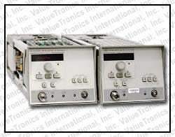
The Agilent 83599A (10 MHz to 50 GHz) and 83598A (2.4 GHz to 50 GHz) are broadband coaxial RF plug-ins designed for the Agilent 8350B sweep oscillator mainframe. Together with the mainframe, they form a swept frequency source that combines wide frequency coverage with high output power and strong harmonic suppression in a single coaxial instrument. The plug-ins use 2.4 mm male output connectors, which the datasheet identifies as the basis for rugged, repeatable broadband coaxial measurements across the full 50 GHz range.
The datasheet identifies three primary applications for the 83599A and 83598A. The first is scalar network analysis, where the plug-ins pair with the Agilent 8757C/E scalar network analyzer and 2.4 mm scalar accessories — including the 85027D directional bridge, 85025D detector, and 11667C power splitter — to test components up to 50 GHz in a coaxial environment. The second is use as a local oscillator for downconverting high-frequency signals, including coaxial noise figure measurements up to 50 GHz when paired with the Agilent 8970B noise figure meter. The third is as a stand-alone source for signal generation and simulation applications that benefit from the plug-ins' broad frequency coverage and modulation flexibility.
ValueTronics International stocks and supports a deep inventory of Agilent and HP-lineage RF and microwave instrumentation — including 8350B mainframes and 83500-series plug-ins — from our 20,000 square-foot secure warehouse at 1675 Cambridge Drive in Elgin, Illinois. Every used instrument is inspected and performance-verified by our technicians before shipment, and the condition grade on each listing reflects what we measured rather than a seller's description. For broadband coaxial sources at this frequency range, where 2.4 mm connector integrity and frequency accuracy directly determine measurement validity, that verification step is the difference between a working instrument and a guess.
Hewlett-Packard's test and measurement business was spun out as Agilent Technologies in 1999, and the electronic measurement portion of Agilent became Keysight Technologies in 2014. Instruments originally branded HP and later relabeled Agilent — including the 8350B mainframe and the 83500-series plug-ins — trace through this same corporate lineage, and customers will encounter these instruments under any of the three names depending on the year of manufacture.
The Agilent 83599A and 83598A are two RF plug-ins in the 83500 series — the family of plug-ins designed for the Agilent 8350B sweep oscillator mainframe. The datasheet describes the 8350B sweeper family as offering a choice of twenty 83500 series plug-ins, and the 83599A and 83598A represent the broadband coaxial options that extend coverage to 50 GHz through 2.4 mm connectors.
The two plug-ins are closely matched in output performance, modulation capability, and accessory ecosystem. They differ primarily in the lower edge of their frequency coverage: the 83599A extends down to 10 MHz, while the 83598A starts at 2.4 GHz. Both reach 50 GHz at the upper end, both use 2.4 mm male output connectors, and both share the same option codes (Option 002 step attenuator, Option 004 rear-panel RF output).
Each pre-owned 83599A or 83598A listed below is its own dedicated product page with condition-matched pricing, accessory documentation, and performance verification specific to that unit. Click through to the model relevant to your frequency coverage requirement to see the current condition grade and what is included.
The choice between the 83599A and 83598A is straightforward: it is determined by whether the application requires coverage below 2.4 GHz. The 83599A's 10 MHz lower limit makes it the broader-coverage choice for applications that span from HF through millimeter-wave frequencies in a single source — including general scalar network analysis where the same instrument must characterize components across a wide band. The 83598A is appropriate when coverage starts at 2.4 GHz, which is the case for many microwave-only applications such as cellular infrastructure testing, radar component characterization, and microwave point-to-point link work.
Output power, harmonic suppression, modulation flexibility, frequency accuracy, and option availability are equivalent between the two plug-ins at frequencies they share. The comparison table that follows summarizes the configuration differences side by side.
| Model | Frequency Range | Max Leveled Power (Normal) | Max Leveled Power (High Power) |
|---|---|---|---|
| 83598A | 2.4 GHz to 50 GHz | +10 dBm (to 20 GHz), +3 dBm (to 40 GHz), 0 dBm (to 50 GHz) | +15 dBm (2.4 to 20 GHz) |
| 83599A | 10 MHz to 50 GHz | +10 dBm (to 20 GHz), +3 dBm (to 40 GHz), 0 dBm (to 50 GHz) | +15 dBm (2.4 to 20 GHz) |
Additional differences in specifications beyond the few shown above are not listed here — see each model's full specifications below.
| Specification | Band 0 | Band 1 | Band 2 | Band 3 | Band 4 | Full Band |
|---|---|---|---|---|---|---|
| Frequency Characteristics | ||||||
| Range (83599A) | 0.01 to 2.4 GHz | 2.4 to 7.0 GHz | 7.0 to 14.0 GHz | 14.0 to 26.5 GHz | 26.5 to 50.0 GHz | 0.01 to 50.0 GHz |
| Range (83598A) | — | 2.4 to 7.0 GHz | 7.0 to 14.0 GHz | 14.0 to 26.5 GHz | 26.5 to 50.0 GHz | 2.4 to 50.0 GHz |
| Accuracy, CW Mode | ±5 MHz | ±5 MHz | ±10 MHz | ±20 MHz | ±25 MHz | — |
| Accuracy, All Sweep Modes | ±15 MHz | ±20 MHz | ±25 MHz | ±50 MHz | ±65 MHz | ±100 MHz |
| Frequency Markers | ±15 MHz, ±0.5% of sweep width | ±20 MHz, ±0.5% of sweep width | ±25 MHz, ±0.5% of sweep width | ±50 MHz, ±0.5% of sweep width | ±65 MHz, ±0.5% of sweep width | ±100 MHz, ±0.5% of sweep width |
| Linearity (typical) | ±2 MHz | ±2 MHz | ±4 MHz | ±10 MHz | ±12 MHz | ±20 MHz |
| Stability with Temperature (typical) | ±200 kHz/°C | ±200 kHz/°C | ±400 kHz/°C | ±800 kHz/°C | ±1.6 MHz/°C | — |
| Stability with 10 dB Power Change | ±100 kHz | ±100 kHz | ±100 kHz | ±200 kHz | ±250 kHz | — |
| Stability with 3:1 Load SWR | ±100 kHz | ±100 kHz | ±100 kHz | ±100 kHz | ±200 kHz | — |
| Stability with Time (typical) | ±100 kHz | ±100 kHz | ±200 kHz | ±400 kHz | ±800 kHz | — |
| Residual FM (peak) | <5 kHz | <5 kHz | <7 kHz | <14 kHz | <24 kHz | — |
| Output Characteristics — Maximum Leveled Power | ||||||
| Normal [High Power] | 10 mW | 10 mW [30 mW] | 10 mW [30 mW] | 10 mW [30 mW] (14 to 20 GHz); 4 mW (20 to 26.5 GHz) | 2 mW (26.5 to 40 GHz); 1 mW (40 to 50 GHz) | 1 mW |
| Option 002 | 10 mW | 7 mW [20 mW] | 7 mW [20 mW] | 7 mW [20 mW] (14 to 20 GHz); 2.5 mW (20 to 26.5 GHz) | 1 mW (26.5 to 40 GHz); 0.5 mW (40 to 50 GHz) | 0.5 mW |
| Option 004 | 10 mW | 7 mW [20 mW] | 7 mW [20 mW] | 7 mW [20 mW] (14 to 20 GHz); 2.5 mW (20 to 26.5 GHz) | 1 mW (26.5 to 40 GHz); 0.5 mW (40 to 50 GHz) | 0.5 mW |
| Power Level Accuracy | ±1.5 dB | ±1.3 dB | ±1.3 dB | ±1.4 dB | ±2.2 dB | ±2.2 dB |
| Power Variations | ±0.9 dB | ±0.7 dB | ±0.7 dB | ±0.8 dB | ±1.4 dB | ±1.5 dB |
| Spurious Signals | ||||||
| Harmonics and Subharmonics, Normal [High Power] | <-25 dBc (0.01 to 1.5 GHz); <-50 dBc (1.5 to 2.4 GHz) | <-45 dBc [<-20 dBc typical] | <-45 dBc [<-20 dBc typical] | <-45 dBc (14 to 20 GHz) [<-20 dBc typical]; -40 dBc (20 to 26.5 GHz) | <-40 dBc (26.5 to 40 GHz); <-35 dBc (40 to 50 GHz) | — |
| Non-harmonics | <-25 dBc | <-50 dBc | <-50 dBc | <-50 dBc | <-50 dBc | — |
| Output Characteristics | Specification |
|---|---|
| Output Power Resolution (Displayed) | 0.1 dB |
| Output Power Resolution (Programmable/Settable) | 0.01 dB |
| Minimum Settable Power | -12 dBm (-72 dBm with Option 002) |
| Power Variation (externally leveled, typical) | ±0.2 dB |
| Power Sweep Calibrated Range | >20 dB (<20 GHz); >12 dB (>20 GHz) |
Please review the Manufacturer's Data Sheet to verify published specifications. Feedback on this webpage is always welcome — please reach out to your Test Architect at any time for questions or concerns. Thank you, we truly appreciate you being our customer.
Model No
Agilent
Condition
Used
Manufacturer
Agilent

30+ Years in Business
Secure Payments
Sell Test Equipments
Knowledgeable Staff
On-site Lab
30+ Years in Business
Secure Payments
Sell Test Equipments
Knowledgeable Staff
On-site Lab
Request A Quote
 Chat Live
 Contact Us
 sales@valuetronics.com