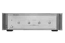
The Agilent 8511B is a four-channel frequency converter test set designed to operate with Agilent 8510 network analyzer systems. As printed on the datasheet, the instrument covers a frequency range of 45 MHz to 50 GHz and provides two reference channels (a1, a2) and two test channels (b1, b2), each accessible through a precision 2.4 mm female front-panel input port.
The 8511B is used to configure measurement setups for a variety of applications within its operating frequency range. The datasheet specifically identifies its use in measuring reflection and transmission parameters of one-port and two-port devices, characterizing antenna parameters, characterizing radar cross sections, and characterizing frequency translation devices. A typical setup illustrated in the datasheet shows the test set integrated with an RF source, a source amplifier, source and reference antennas, an antenna under test, a positioner and controller, and the 8510 receiver.
The 8511B carries Agilent Technologies branding. Agilent Technologies was spun off from Hewlett-Packard in 1999 when HP separated its test and measurement business from its computing business. In 2014, Agilent further divided, and the electronic measurement product line — including the 8510 network analyzer family and its associated test sets — transitioned to Keysight Technologies. Documentation for this instrument carries the Agilent brand name with a transition notice acknowledging that the products previously shipped under Hewlett-Packard and continue under Keysight.
The 8511B is a four-channel frequency converter test set within the 8510 network analyzer ecosystem. As described in the datasheet, it covers 45 MHz to 50 GHz with precision 2.4 mm input ports and is configured for both standard and multi-test-set system architectures.
Within the catalog, the 8511B is differentiated primarily by its option configuration. The base instrument provides four channels of frequency conversion with standard IF routing. Option 001 adds IF switching electronics that allow the instrument to participate in a multi-test-set chain controlled by a single 8510.
Each pre-owned 8511B listed below is its own product page with condition-matched pricing and inventory. Selecting the configuration that matches your option requirements (base versus Option 001) and your preferred condition tier directs you to the correct listing for ordering.
The 8511B in its base configuration provides direct IF output from each of its four samplers to the 8510 via the rear-panel J11 Test Set Interconnect. The Option 001 variant of the 8511B adds an internal IF multiplexer that routes a 20 MHz IF signal from a connected downstream test set through to the 8510, enabling up to four test sets to share one 8510 controller.
The functional difference between base and Option 001 8511B units is the addition of the J10 Test Set Interconnect on Option 001 instruments. On a base unit, only J11 (output to the 8510) is populated; on an Option 001 unit, J10 (input from a downstream test set) is also present and connects through the internal IF multiplexer. A single chain may contain a mix of Option 001 and base instruments, with the last test set in the chain not requiring Option 001.
Other documented options affect documentation and mounting hardware rather than measurement function: Option 908 provides rack-mount hardware with handles removed, Option 910 provides a duplicate manual, and Option 913 provides rack-mount hardware with handles attached. Options 1BN and 1BP add MIL-STD 45662A Certificate of Calibration documentation as configured at order time.
| Model | Frequency Range | Input Channels | Connector Type |
|---|---|---|---|
| 8511B | 45 MHz to 50 GHz | 4 (a1, b1, a2, b2) | 2.4 mm female |
Additional differences in specifications beyond the few shown above are not listed here — see each model's full specifications below.
| Parameter | 0.045 to 8 GHz | 8 to 20 GHz | 20 to 40 GHz | 40 to 50 GHz |
|---|---|---|---|---|
| Frequency Response Tracking - Magnitude (ripple) | ±1.5 dB | ±1.5 dB | ±1.5 dB | ±1.5 dB |
| Frequency Response Tracking - Phase (ripple) | ±75 degrees | ±75 degrees | ±75 degrees | ±75 degrees |
| Frequency Response Tracking - Magnitude slope | ±0.055 dB/GHz | ±0.055 dB/GHz | ±0.055 dB/GHz | ±0.055 dB/GHz |
| Crosstalk | −85 dB | −85 dB | −75 dB | −70 dB |
| High Level Noise - Magnitude (ratio) | 0.006 dB rms | 0.009 dB rms | 0.040 dB rms | 0.060 dB rms |
| High Level Noise - Phase (ratio) | 0.08 degrees rms | 0.145 degrees rms | 0.245 degrees rms | 0.400 degrees rms |
| Low Level Noise | −100 dBm | −102 dBm | −102 dBm | −102 dBm |
| Conversion Gain | 1 dB to −4 dB | 1 dB to −4 dB | −3 dB to −13 dB | −5 dB to −15 dB |
| Compression (0.1 dB point) | −10 dBm | −10 dBm | −15 dBm | −20 dBm |
| Input Port Impedance Match (return loss, all 4 ports) | ≥17 dB | ≥15 dB | ≥9 dB | ≥7 dB |
| Dynamic Range (all inputs) | 110 dB (−10 to −120 dBm) | 112 dB (−10 to −122 dBm) | 107 dB (−15 to −122 dBm) | 102 dB (−20 to −122 dBm) |
| Accuracy Enhanced Crosstalk | −115 dB | −115 dB | −113 dB | −110 dB |
| Port input power for phase lock (min) | −41 dBm | −39 dBm | −32 dBm (20 to 26.5 GHz) | −30 dBm |
| Port input power for phase lock (max) | −5 dBm | −5 dBm | −5 dBm | −5 dBm |
Please review the Manufacturer's Data Sheet to verify published specifications. Feedback on this webpage is always welcome — please reach out to your Test Architect at any time for questions or concerns. Thank you, we truly appreciate you being our customer.
Model No
Agilent
Condition
Used
Manufacturer
Agilent

30+ Years in Business
Secure Payments
Sell Test Equipments
Knowledgeable Staff
On-site Lab
30+ Years in Business
Secure Payments
Sell Test Equipments
Knowledgeable Staff
On-site Lab
Request A Quote
 Chat Live
 Contact Us
 sales@valuetronics.com