


🎓 Request a Quote To Get An EDU Discount
Couldn't load pickup availability
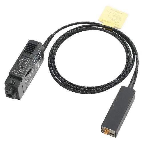
The Tektronix TIVP1, TIVP05, and TIVP02 are IsoVu Generation 2 isolated measurement systems — high voltage differential probes that use power-over-fiber and an optical analog signal path to provide complete galvanic isolation between the measurement system and the device under test. By letting the probe float independently at the common mode voltage, the IsoVu architecture delivers accurate differential measurements up to ±2500 V on reference voltages slewing ±60 kV at 100 V/ns or faster. The Generation 2 design packages this capability at one-fifth the size of first-generation IsoVu probes.
These probes are built for floating measurements in power converter and motor drive designs. Listed applications include half- and full-bridge designs using SiC or GaN, FETs, or IGBTs; floating measurements; power converter design; power device evaluation; switching power supply design; inverter design; motor drive design; electronic ballast design; EMI and ESD troubleshooting; and current shunt measurements. Making high-side measurements in half-bridge power converters is challenging because the source or collector to which the measurements are referenced is slewing rapidly up and down; wide bandgap devices such as SiC and GaN FETs are harder still because they can switch high voltages in a few nanoseconds, and the resulting common mode noise leaks into the differential measurement and hides VGS and VDS detail.
The IsoVu Generation 2 family — TIVP1, TIVP05, and TIVP02 — shares a single isolated measurement architecture and differs primarily in bandwidth. Tektronix offers the series at bandwidths of 200 MHz, 500 MHz, and 1 GHz so the buyer can match isolation performance to budget and application. All three models use the same power-over-fiber optical isolation, the same ±60 kV common mode voltage range, and the same sensor tip cable ecosystem.
Across the series, the differential input voltage range (up to ±2500 V), the offset range (up to ±2500 V), and the 160 dB common mode rejection at DC are set by the selected sensor tip cable rather than by the model. A buyer therefore chooses the model for its bandwidth and rise-time class, then selects tip cables for the required differential voltage range.
Each new model below is its own dedicated product page with condition-matched pricing. Select the model whose bandwidth and rise-time class fit your measurement, then choose the page that matches the condition you need.
The models separate on bandwidth and rise time. The TIVP1 provides 1 GHz bandwidth with a 450 ps rise time, the TIVP05 provides 500 MHz with an 850 ps rise time, and the TIVP02 provides 200 MHz with a 2 ns rise time. See the comparison table below for the per-model values.
Beyond bandwidth and rise time, the three models are specified identically: each carries the ±60 kV common mode voltage range, the up-to-±2500 V differential and offset ranges set by sensor tip cable, common mode input capacitance under 2 pF, and differential DC gain accuracy better than 2%. The choice between them is a bandwidth-versus-budget decision rather than a difference in isolation capability.
| Model | Bandwidth | Rise Time | Max Differential Voltage |
|---|---|---|---|
| TIVP02 | 200 MHz | 2 ns | ±2500 V |
| TIVP1 | 1 GHz | 450 ps | ±2500 V |
| TIVP05 | 500 MHz | 850 ps | ±2500 V |
Additional differences in specifications beyond the few shown above are not listed here — see each model's full specifications below.
| Specification | Value |
|---|---|
| Overview (Typical; apply to all models unless noted) | |
| Bandwidth | TIVP1: 1 GHz | TIVP05: 500 MHz | TIVP02: 200 MHz |
| Rise time | TIVP1: 450ps | TIVP05: 850ps | TIVP02: 2ns |
| Differential Input Voltage Range, Offset Range, Differential Impedance (use only the sensor tip cables listed) | |
| SMA Input (50 Ω mode) | Differential input voltage range: ±5 V | Offset range: ±25 V | Input impedance: 50 Ω || N.A. |
| SMA Input (1 MΩ mode) | Differential input voltage range: ±5 V | Offset range: ±25 V | Input impedance: 1 MΩ || 11 pF |
| TIVPMX10X | Differential input voltage range: ±50 V | Offset range: ±200 V | Input impedance: 10 MΩ || 2.8 pF |
| TIVPMX50X | Differential input voltage range: ±250 V | Offset range: ±250 V | Input impedance: 10 MΩ || <5 pF* |
| TIVPSQ100X | Differential input voltage range: ±500 V | Offset range: ±500 V | Input impedance: 10 MΩ || <5 pF* |
| TIVPWS500X | Differential input voltage range: ±2.5 kV | Offset range: ±2.5 kV | Input impedance: 40 MΩ || <4 pF* |
| TIVPMX1X | Differential input voltage range: ±5 V | Offset range: ±25 V | Input impedance: 50 Ω or 1 MΩ || 11 pF |
| Common Mode Rejection Ratio (CMRR) | |
| SMA Input (50 Ω mode) | DC: 160 dB | 1 MHz: 145 dB | 100 MHz: 100 dB | 200 MHz: 100 dB | 500 MHz: 100 dB | 1 GHz: 90 dB |
| SMA Input (1 MΩ mode) | DC: 160 dB | 1 MHz: 145 dB | 100 MHz: 100 dB | 200 MHz: 100 dB | 500 MHz: 100 dB | 1 GHz: 90 dB |
| TIVPMX10X | DC: 160 dB | 1 MHz: 115 dB | 100 MHz: 92 dB | 200 MHz: 90 dB | 500 MHz: 85 dB | 1 GHz: 80 dB |
| TIVPMX50X | DC: 160 dB* | 1 MHz: 104 dB* | 100 MHz: 85 dB* | 200 MHz: 80 dB* | 500 MHz: 73 dB* | 1 GHz: 70 dB* |
| TIVPSQ100X | DC: 160 dB* | 1 MHz: 100 dB* | 100 MHz: 70 dB* | 200 MHz: 57 dB* | 500 MHz: 39 dB* | 1 GHz: 30 dB* |
| TIVPWS500X | DC: 160 dB* | 1 MHz: 100 dB* | 100 MHz: 60 dB* | 200 MHz: 48 dB* | 500 MHz: 33 dB* | 1 GHz: 25 dB* |
| TIVPMX1X | DC: 160 dB* | 1 MHz: 145 dB* | 100 MHz: 100 dB* | 200 MHz: 100 dB* | 500 MHz: 100 dB* | 1 GHz: 90 dB* |
| Maximum Non-Destructive Differential Voltage, Vpk (DC + peak AC) | |
| SMA Input (50 Ω mode) | 5 V RMS |
| SMA Input (1 MΩ mode) | 100 Vpk |
| TIVPMX10X | 250 Vpk |
| TIVPMX50X | 300 Vpk* |
| TIVPSQ100X | 600 Vpk* |
| TIVPWS500X | 3300 Vpk* |
| TIVPMX1X | 5 V RMS (50 Ω), 100 Vpk (1 MΩ) |
| Common Mode | |
| Common mode voltage range | 60 kV peak |
| Common mode input resistance (Typical) | Galvanically isolated through the fiber optic connection |
| Common mode input capacitance (Typical) | <2 pF |
| DC Gain Accuracy | |
| Differential DC gain accuracy | <2% |
| System Noise (rms) | |
| SMA Input (50 Ω mode) | ±20 mV range: 0.43 mV rms | ±320 mV range: 1.46 mV rms | ±5 V range: 48 mV rms |
| SMA Input (1 MΩ mode) | ±20 mV range: 0.43 mV rms | ±320 mV range: 1.46 mV rms | ±5 V range: 48 mV rms |
| TIVPMX10X | ±20 mV range: 4.3 mV rms | ±320 mV range: 14.6 mV rms | ±5 V range: 480 mV rms |
| TIVPMX50X | ±20 mV range: 21.5 mV rms* | ±320 mV range: 73 mV rms* | ±5 V range: 2.4 V rms* |
| TIVPSQ100X | ±20 mV range: 43 mV rms* | ±320 mV range: 146 mV rms* | ±5 V range: 4.8 V rms* |
| TIVPWS500X | ±20 mV range: 215 mV rms* | ±320 mV range: 730 mV rms* | ±5 V range: 24 V rms* |
| Propagation Delay | |
| 2 meter cable | 18.3 ns |
| 10 meter cable | 57.3 ns* |
| Laser Certification | |
| Laser class | CLASS I LASER PRODUCT |
| Compliance | Complies with 21 CFR 1040.10 and 1040.11 except for deviations pursuant to Laser Notice No. 50, dated June 24, 2007. |
Important: Use only the sensor tip cables listed.
Important: Maximum non-destructive differential voltage is derated with frequency; refer to the Maximum differential input voltage vs. frequency derating graph in the TIVP Series IsoVu Measurement System User Manual.
Important: The standard delivery includes the TIVPMX10X MMCX probe tip (±50 V differential range). Higher-voltage sensor tip cables — TIVPMX50X (±250 V), TIVPSQ100X (±500 V), and TIVPWS500X (±2.5 kV) — are recommended accessories that must be ordered separately to reach the probe's higher differential voltage ranges; additional 0.100" and 0.200" spaced square-pin tips are required for applications that require greater than ±250 V differential voltage.
Important: Probes and accessories are not covered by the oscilloscope warranty and Service Offerings; refer to the datasheet of each probe and accessory model for its unique warranty and calibration terms.
This is a brand-new, factory-sealed unit, supplied exactly as it arrives from the manufacturer and backed by the full manufacturer warranty. For the exact configuration, available options, included accessories, or current lead time for your application, our Test Architects can confirm the details before you order.
ValueTronics supplies both new and used test and measurement equipment. New units ship factory-sealed, exactly as received from the manufacturer; every used unit is inspected and functionally verified in-house at our 20,000 sq ft secure facility in Elgin, Illinois before it ships. Our Test Architects can help you select the condition, calibration, and configuration that fit your application.
Please review the Manufacturer's Data Sheet to verify published specifications. Feedback on this webpage is always welcome — please reach out to your Test Architect at any time for questions or concerns. Thank you, we truly appreciate you being our customer.
Model No
Tektronix
Condition
Factory New
Manufacturer
Tektronix
Volt_prob_freq
200 MHz
Volt_prob_volts
±2500 V
TIVPMX1X Tektronix Accessory New
TIVPMX1X
TIVPMX50X Tektronix Accessory New
TIVPMX50X
TIVPSQ100X Tektronix Accessory New
TIVPSQ100X
TIVPWS500X Tektronix Accessory New
TIVPWS500X

30+ Years in Business
Secure Payments
Sell Test Equipments
Knowledgeable Staff
On-site Lab
30+ Years in Business
Secure Payments
Sell Test Equipments
Knowledgeable Staff
On-site Lab
Request A Quote
 Chat Live
 Contact Us
 sales@valuetronics.com