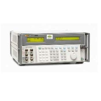
The Fluke 5800A Oscilloscope Calibrator is a precision calibration source designed to verify and calibrate the performance of oscilloscopes across voltage, time, frequency, and impedance parameters. The instrument provides discrete calibration functions including DC and square wave voltage outputs, edge signals for rise time verification, leveled sine waves for bandwidth measurement, time markers for timebase calibration, wave and pulse generators, and oscilloscope input impedance and capacitance measurement capabilities.
Oscilloscope calibrators are used by metrology laboratories, calibration service providers, and instrument manufacturers to verify oscilloscope performance against published specifications. The 5800A supports calibration of oscilloscope voltage accuracy, timebase accuracy, bandwidth and flatness, rise time response, input impedance, and trigger functionality. The included TV trigger signal output with selectable NTSC, SECAM, and PAL-M frame formats supports calibration of oscilloscopes used in broadcast and video applications.
Fluke Corporation, headquartered in Everett, Washington, has manufactured precision electronic test instruments since 1948. Fluke was acquired by Danaher Corporation in 1998 and was subsequently transferred to Fortive Corporation when Danaher spun off its industrial businesses in 2016. The Fluke brand and product lines have remained continuous through these corporate transitions, with calibration and metrology products continuing under the established Fluke name.
| Function | Specification |
|---|---|
| Volt Function | |
| DC Signal Amplitude Range (into 50Ω) | 0V to ±6.6V |
| DC Signal Amplitude Range (into 1 MΩ) | 0V to ±130V |
| Square Wave Signal Amplitude Range (into 50Ω) | ±1 mV to ±6.6V p-p |
| Square Wave Signal Amplitude Range (into 1 MΩ) | ±1 mV to ±130V p-p |
| DC 1-Year Absolute Uncertainty, tcal ±5°C (into 50Ω) | ±(0.25% of output + 40 µV) |
| DC 1-Year Absolute Uncertainty, tcal ±5°C (into 1 MΩ) | ±(0.025% of output + 25 µV) |
| Square Wave 1-Year Absolute Uncertainty (into 50Ω) | ±(0.25% of output + 40 µV) |
| Square Wave 1-Year Absolute Uncertainty (into 1 MΩ) | ±(0.05% of output + 5 µV) |
| Sequence | 1-2-5 (e.g., 10 mV, 20 mV, 50 mV) |
| Frequency Range | 10 Hz to 10 kHz |
| Edge Function (into 50Ω) | |
| Amplitude Range (p-p) | 4.0 mV to 2.5V |
| Frequency Range | 1 kHz to 10 MHz |
| Rise Time | ≤300 ps |
| 1-Year Absolute Uncertainty: Amplitude | ±(2% of output + 200 µV) |
| 1-Year Absolute Uncertainty: Frequency | ±(2.5 ppm of setting) |
| 1-Year Absolute Uncertainty: Rise Time | (+0 ps / -100 ps) |
| Typical Jitter, Edge to Trigger | <5 ps (p-p) |
| Leading Edge Aberrations: Within 2 ns from 50% of rising edge | <(3% of output + 2 mV) |
| Leading Edge Aberrations: 2 ns to 5 ns | <(2% of output + 2 mV) |
| Leading Edge Aberrations: 5 ns to 15 ns | <(1% of output + 2 mV) |
| Leading Edge Aberrations: after 15 ns | <(0.5% of output + 2 mV) |
| Tunnel Diode Pulse Drive | Square wave at 100 Hz to 100 kHz, with variable amplitude of 60V to 100V p-p |
| Leveled Sine Wave Function (into 50Ω) | |
| Amplitude Range (p-p) | 5 mV to 5.5V |
| 1-Year Absolute Uncertainty @ 50 kHz (reference) | ±(2% of output + 300 µV) |
| 1-Year Absolute Uncertainty, 50 kHz to 100 MHz | ±(3.5% of output + 300 µV) |
| 1-Year Absolute Uncertainty, 100 MHz to 300 MHz | ±(4% of output + 300 µV) |
| 1-Year Absolute Uncertainty, 300 MHz to 600 MHz | ±(6% of output + 300 µV) |
| Flatness (relative to 50 kHz), 50 kHz to 100 MHz | ±(1.5% of output + 100 µV) |
| Flatness, 100 MHz to 300 MHz | ±(2% of output + 100 µV) |
| Flatness, 300 MHz to 600 MHz | ±(4% of output + 100 µV) |
| Short-term Amplitude Stability | ≤1% (within one hour after reference amplitude setting, ±5°C) |
| Frequency Resolution | 10 kHz |
| Frequency 1-Year Absolute Uncertainty | ±1 ppm |
| Distortion: 2nd Harmonic | ≤-33 dBc |
| Distortion: 3rd and Higher Harmonics | ≤-38 dBc |
| Time Marker Function (into 50Ω) | |
| 1-Year Absolute Uncertainty, 5s to 50 ms | ±(2.5 ppm + 5 µHz) |
| 1-Year Absolute Uncertainty, 20 ms to 100 ns | ±1 ppm |
| 1-Year Absolute Uncertainty, 50 ns to 20 ns | ±1 ppm |
| 1-Year Absolute Uncertainty, 10 ns | ±1 ppm |
| 1-Year Absolute Uncertainty, 5 ns to 2 ns | ±1 ppm |
| Wave Shape, 5s to 50 ms | Pulsed, sawtooth or square |
| Wave Shape, 20 ms to 100 ns | Pulsed, sawtooth, square, 1/5 pulse |
| Wave Shape, 50 ns to 20 ns | Pulsed, sawtooth or square |
| Wave Shape, 10 ns | Square or sine |
| Wave Shape, 5 ns to 2 ns | Sine |
| Typical Jitter (p-p), 5s to 50 ms | <10 ppm |
| Typical Jitter (p-p), all other ranges | <1 ppm |
| Sequence | 5-2-1 from 5s to 2 ns (e.g., 500 ms, 200 ms, 100 ms) |
| Wave Generator (Square, Sine, Triangle into 50Ω or 1 MΩ) | |
| Amplitude Range (into 1 MΩ) | 1.8 mV to 55V p-p |
| Amplitude Range (into 50Ω) | 1.8 mV to 2.5V p-p |
| 1-Year Absolute Uncertainty, tcal ±5°C, 10 Hz to 10 kHz | ±(3% of p-p output + 100 µV) |
| Typical DC Offset Range | 0 to ±(≥40% of p-p amplitude); dc offset plus wave signal must not exceed 30V rms |
| Frequency Range | 0.01 Hz to 100 kHz |
| Pulse Generator (Positive Pulse into 50Ω) | |
| Typical Rise/Fall Times | ≤1.5 ns |
| Amplitude Available | Discrete steps: 1V, 250 mV, 100 mV, 25 mV, 10 mV |
| Pulse Width Range | 4 ns to 500 ns (not to exceed 40% of period) |
| Pulse Width Uncertainty (typical) | 5% + 2 ns |
| Pulse Period Range | 20 ms to 200 ns (50 Hz to 5.0 MHz) |
| Pulse Period 1-Year Absolute Uncertainty | ±1 ppm |
| Trigger Functions | |
| External Trigger Functions | Available for pulse, time mark, edge and voltage generator functions |
| TV Trigger Frame Formats | Selectable NTSC, SECAM, PAL, PAL-M |
| TV Trigger Polarity | Selectable inverted or uninverted video |
| TV Trigger Line Marker | Selectable Line Video Marker |
| Measurement Functions (Oscilloscope Input Impedance) | |
| Resistance Range / Uncertainty: 40Ω to 60Ω | 0.1% |
| Resistance Range / Uncertainty: 500 kΩ to 1.5 MΩ | 0.1% |
| Capacitance Range / Uncertainty: 5 pF to 50 pF | 5% ±0.5 pF |
| Overload Measurement Function | |
| Source Voltage | 5V to 9V |
| Typical Maximum Time Limit dc or ac 1 kHz ac | Settable from 5 to 60 sec |
| Auxiliary Input | |
| Frequency Range | Up to 2 GHz |
| Voltage Range | 0-40V p-p |
| VSWR | <1.7 @ 2 GHz |
| External Frequency Reference Input | |
| Reference Frequency | 10 MHz |
| General Specifications | |
| Warm-up Time | Twice the time since last warmed up, to a maximum of 30 minutes |
| Settling Time | 5 seconds or faster for all functions and ranges |
| Standard Interfaces | IEEE-488 (GPIB), RS-232 |
| Temperature: Operating | 0 °C to 50 °C |
| Temperature: Calibration (tcal) | 15 °C to 35 °C |
| Temperature: Storage | -20 °C to 70 °C |
| Temperature Coefficient | 0.1X/°C of 1-year specification for temperatures outside tcal +5 °C |
| Relative Humidity: Operating | <80% to 30 °C, <70% to 40 °C, <40% to 50 °C |
| Relative Humidity: Storage | <95%, non-condensing |
| Altitude: Operating | 3,050m (10,000 ft) maximum |
| Altitude: Non-operating | 12,200m (40,000 ft) maximum |
Please review the Manufacturer's Data Sheet to verify published specifications. Feedback on this webpage is always welcome — please reach out to your Test Architect at any time for questions or concerns. Thank you, we truly appreciate you being our customer.
Model No
Fluke
Condition
Used
Manufacturer
Fluke

30+ Years in Business
Secure Payments
Sell Test Equipments
Knowledgeable Staff
On-site Lab
30+ Years in Business
Secure Payments
Sell Test Equipments
Knowledgeable Staff
On-site Lab
Request A Quote
 Chat Live
 Contact Us
 sales@valuetronics.com