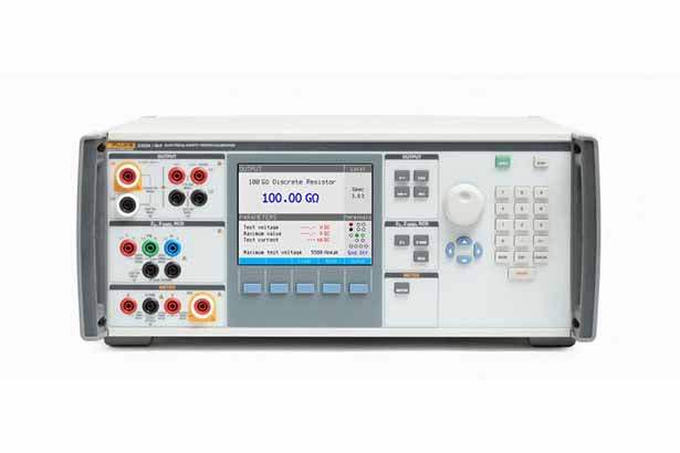
The Fluke Calibration 5322A Electrical Safety Tester Calibrator is a single-instrument solution for calibrating the full range of electrical safety test equipment found in modern calibration laboratories. It replaces discrete resistors, decade boxes, and other custom solutions traditionally assembled to verify electrical safety testers, consolidating multiple sourcing and measurement functions into one chassis with a unified user interface, GPIB and USB control, and MET/CAL compatibility for automated workflows.
The 5322A is designed to calibrate insulation resistance testers (megohm meters), leakage current testers, multifunction installation testers, portable appliance testers (PATs), continuity testers, earth (ground) resistance testers, loop/line impedance testers, ground bond testers, residual-current device (RCD) and ground fault circuit interrupter (GFCI) testers, and hipot testers. It supports compliance with international standards including BS 7671 17th Edition (UK), IEC/EN 60364, EN 50191, EN 61557, EN 60990, AS/NZS 3000 (Australia/New Zealand), and Chinese verification regulations JJG 622-1997, JJG 1005-2005, JJG 366-2004, JJG 984-2004, JJG 843-2007, JJG 795-2016, and JJF 1283-2011.
ValueTronics stocks, inspects, and tests every 5322A configuration from our 20,000 sq ft secure warehouse at 1675 Cambridge Drive, Elgin, Illinois. Unlike drop-shippers and pass-through brokers, we physically handle every unit that ships from us. Our team can confirm option suffixes, accessory completeness, calibration documentation status, and condition before quoting — so when you receive a 5322A from us, you receive the exact configuration described in our listing.
The 5322A family consists of eight ordering configurations built around a common chassis. All variants share the same low-resistance source, ground bond and line/loop impedance resistor banks, leakage current simulation, RCD simulation for both installation testers and PATs, integrated multimeter, hipot timer and distortion analysis functions, GPIB/USB interfaces, and the standard accessory bundle (R-Multiplier, 10 kV divider, RCD-PAT adapter, PAT-LOAD adapter, HV test lead set, and region-specific line cord and adapters).
The configurations differ along three independent option axes: the high-voltage resistance source range (1.5 kV base versus 5 kV with the /5 option), the inclusion of a 600 V AC/DC voltage source with active loop compensation (the /VLC option), and the inclusion of a characterized 40 kV high-voltage probe (the /40 option). Customers select the combination that matches their workload mix between standard hipot calibration, high-voltage hipot calibration, voltage measurement function calibration, and ultra-high-voltage hipot work above 10 kV.
Each pre-owned 5322A configuration linked below is its own product page with condition-matched pricing and current availability. The configurations are not interchangeable — option suffixes are factory-installed and cannot be added in the field, so the configuration you order is the configuration that ships. Review each model page for the specific option set, accessory list, and any calibration documentation status before placing your order.
The base 5322A provides 1.5 kV continuously variable high-voltage resistance sourcing from 10 kΩ to 10 GΩ — appropriate for calibrating insulation testers rated to 1 kV or for higher-voltage testers when paired with the included R-Multiplier (extending the range to 10 TΩ at 10 kV). The 5322A/5 upgrades the internal high-voltage resistance source to 5.5 kV with the range extended to 100 GΩ, eliminating the need for the R-Multiplier on most 5 kV-rated insulation tester calibrations and providing higher inherent accuracy for hipot DC voltage sourcing. The /VLC option adds a 600 V AC/DC voltage source with 4-digit resolution across 40 Hz to 400 Hz (useful for calibrating the voltage measurement function of multifunction testers and PATs and for powering PAT testers during calibration) plus the active loop compensation feature, which cancels residual line impedance during loop/line impedance tester calibration. The /40 option adds the characterized 80K-40 high-voltage probe, extending the meter's voltage measurement capability to 40 kV with ±(0.5% of input + 10 V) uncertainty for hipot calibration above the 10 kV range covered by the included 10 kV divider.
Compare the ordering configurations in the table below to match the option set to your specific workload. Customers calibrating only sub-1 kV insulation testers and standard PATs are typically served by the base 5322A. Labs working with 5 kV hipot testers benefit from the /5 option's direct sourcing capability. The /VLC option is appropriate where the workload includes voltage measurement function calibration or active loop compensation requirements.
| Model | High Resistance Source | 600 V AC/DC Source | 40 kV Probe |
|---|---|---|---|
| 5322A | 1.5 kV | No | No |
| 5322A/5 | 5 kV | No | No |
| 5322A/40 | 1.5 kV | No | Yes |
| 5322A/VLC | 1.5 kV | Yes | No |
Additional differences in specifications beyond the few shown above are not listed here — see each model's full specifications below.
| General Specifications | |
|---|---|
| Specifications confidence level | 99 % |
| Specifications interval | 1 year |
| Power line | 115/230 V ac (50/60 Hz) +10 % / -14 %, with the maximum voltage difference between neutral and protective earth not exceeding 15 V |
| Power consumption | 1250 VA maximum |
| AC mains input fuse | 2 A, 250 V for 230 V, time delay (T2L250 V – 5 mm x 20 mm); 4 A, 250 V for 115 V, time delay (T4L250 V – 5 mm x 20 mm) |
| RCD input fuse | 3.15 A, 250 V, fast (F3.15H250 V – 5 mm x 20 mm) |
| Meter amps (A) input fuse | 20 A, 500 V, time delay (F20H500 V – 6.3 mm x 32 mm) |
| Loop/Line impedance input fuse | 4 A, 500 V, time delay (T4H500 V – 6.3 mm x 32 mm) |
| Leakage current input fuse | 100 mA, 250 V, fast (F100 mL250 V – 5 mm x 20 mm) |
| Warm-up time | 15 minutes |
| Operating temperature | 18 °C to 28 °C |
| Calibration temperature (tcal) | 23 °C |
| Storage temperature | -10 °C to 50 °C |
| Storage recovery time | Typically <24 hours at operating temperature |
| Relative humidity (operating) | <80 % to 28 °C (resistance outputs >10 GΩ specified for <70 % to 28 °C) |
| Relative humidity (storage) | <90 % non-condensing 0 °C to 50 °C |
| Operating altitude | 3050 m (10 000 ft) |
| Storage altitude | 12 200 m (40 000 ft) |
| Dimensions | 430 mm x 555 mm x 170 mm (16.9 in x 21.8 in x 6.7 in) |
| Weight | 20 kg (44.1 lb) |
| Safety (Mains) | IEC 61010-1: Overvoltage category II, pollution degree 2 |
| Safety (Measurement) | IEC 61010-2-030: 5000 V (not category rated) |
| EMC (International) | IEC 61326-1: Basic electromagnetic environment; CISPR 11: Group 1, Class A |
| EMC (Korea KCC) | Class A equipment (industrial broadcasting & communication equipment) |
| EMC (USA FCC) | 47 CFR 15 subpart B; considered an exempt device per clause 15.103 |
| Communication interfaces | IEEE 488 (GPIB) and USB |
| Low Resistance Source | |
|---|---|
| Range | 100 mΩ to 10 kΩ + 10 mΩ single value selection, dc and line frequency (50/60 Hz) |
| Setting resolution | 3.5 digits (continuously variable) |
| Test current measurement range | 0 mA to 1000 mA (ac + dc) rms |
| Short mode nominal resistance (2-wire) | <100 mΩ |
| Short mode maximum current | 1000 mA (ac + dc) rms |
| Open mode nominal resistance | 30 MΩ ± 20 % |
| Open mode max input voltage | 50 V (ac + dc) rms |
| Open mode test voltage reading | 0 V to 50 V (ac + dc) rms; resolution 1 V; uncertainty ± (5 % + 2 V) |
| Lead resistance simulation (4-wire mode) | 500 Ω, 1 kΩ, 2 kΩ, 5 kΩ ± 2 %, inserted as pairs |
| 1.5 kV High Resistance Source (DC only) — base 5322A models | |
|---|---|
| Range | 10 kΩ to 10 GΩ + 100 GΩ single value selection |
| Resolution | 4.5 digit (continuously variable for 10 kΩ to 10 GΩ range) |
| Test voltage measurement range | 1200 V dc in resistance range from 10 kΩ to 1 MΩ; 2000 V dc in resistance range 1 MΩ to 100 GΩ |
| Short mode nominal resistance | < 250 Ω |
| Short mode test current range / uncertainty | 0 mA dc to 50 mA dc; 0.1 mA resolution; ± (2 % + 0.5 mA) |
| Settling time | 2 seconds for input deviations of <5 % |
|---|---|
| Test current measurement range | 0 mA dc to 9.9 mA dc |
| Test current uncertainty | ± (1.5 % + 5V/R A), where R is the selected resistance value |
| Short mode max input current | 50 mA dc |
| Range of lead resistance compensation | 0 Ω to 2.000 Ω |
|---|
Please review the Manufacturer's Data Sheet to verify published specifications. Feedback on this webpage is always welcome — please reach out to your Test Architect at any time for questions or concerns. Thank you, we truly appreciate you being our customer.
Model No
Fluke
Condition
Used
Manufacturer
Fluke

30+ Years in Business
Secure Payments
Sell Test Equipments
Knowledgeable Staff
On-site Lab
30+ Years in Business
Secure Payments
Sell Test Equipments
Knowledgeable Staff
On-site Lab
Request A Quote
 Chat Live
 Contact Us
 sales@valuetronics.com