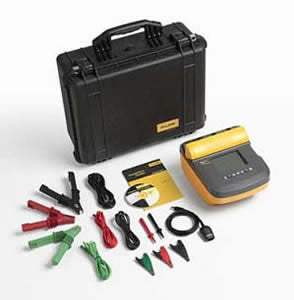
The Fluke 1555 is a digital insulation resistance tester that delivers test voltages up to 10 kV, making it suitable for evaluating insulation integrity on a wide range of high-voltage equipment. The companion Fluke 1550C provides the same core measurement architecture with test voltages up to 5 kV. Both instruments conduct the full range of test voltages specified in IEEE 43-2000 and carry a CAT III 1000 V / CAT IV 600 V safety rating.
The datasheet positions these testers for use on switchgear, motors, generators, and cables. With measurement storage and a PC interface, they are described as tools for preventative or predictive maintenance programs intended to identify potential equipment failures before they occur. An insulation resistance tester applies a known DC voltage across an insulation barrier and measures the resulting leakage current, allowing the technician to evaluate the condition of the dielectric material that separates energized conductors from ground or from each other.
Fluke Corporation was founded in 1948 by John Fluke Sr. in Seattle, Washington, and built its reputation on rugged, accurate field instruments — particularly digital multimeters and electrical test equipment. Fluke was acquired by Danaher Corporation, and in 2016 transitioned to Fortive Corporation when Danaher spun off its industrial businesses. The Fluke brand and product lines have been maintained continuously through these corporate transitions, with the insulation tester line representing one of Fluke's longstanding categories alongside multimeters, clamp meters, and calibration instruments.
The Fluke 1550 series consists of two digital insulation resistance testers that share a common platform and differ primarily in their maximum test voltage. The 1550C provides test voltages up to 5 kV; the 1555 extends the range to 10 kV. Both models implement the full set of intermediate test voltages — 250 V, 500 V, 1000 V, 2500 V, and 5000 V — with the 1555 adding the 10000 V capability for testing equipment that requires the higher stress level.
Beyond the maximum test voltage, the two instruments share identical core specifications: the same CAT III 1000 V / CAT IV 600 V safety rating, the same DAR and PI automatic calculation, the same 99-location measurement storage with PC interface, the same guard system architecture, the same live circuit warning, and the same timer, leakage current, and capacitance measurement ranges. The choice between models is driven by the test voltage requirements of the equipment being maintained rather than by differences in measurement quality or feature set.
Each new model below is its own dedicated product page with condition-matched pricing, current availability, and accessory details. Confirm the specific configuration on the linked page before placing an order.
The primary differentiator in the comparison table is the maximum test voltage. The 1550C tops out at 5 kV with a resistance measurement range to 1 TΩ on that range; the 1555 extends to 10 kV with a resistance range to 2 TΩ. For applications where the highest test voltage required is 5 kV — which covers the majority of medium-voltage motors, generators, and cables in industrial maintenance programs — the 1550C provides the complete capability set.
The 1555 is the appropriate selection when the application requires testing above 5 kV, such as higher-voltage rotating machinery, transmission-class cables, or any equipment specified for testing per IEEE 43-2000 at the 10 kV level. Both models share the same physical dimensions, weight, and battery system, so the operational footprint and field-service ergonomics are identical regardless of which voltage tier is selected.
| Model | Max Test Voltage | Max Resistance Range | Safety Rating |
|---|---|---|---|
| 1555/Kit | 10 kV | 2 TΩ | CAT III 1000 V, CAT IV 600 V |
| 1550C | 5 kV | 1 TΩ | CAT III 1000 V, CAT IV 600 V |
| 1555 | 10 kV | 2 TΩ | CAT III 1000 V, CAT IV 600 V |
| 1550C/Kit | 5 kV | 1 TΩ | CAT III 1000 V, CAT IV 600 V |
Additional differences in specifications beyond the few shown above are not listed here — see each model's full specifications below.
| Specification | Value |
|---|---|
| Insulation Resistance Measurement | |
| 250 V test voltage range | 200 kΩ to 5 GΩ (±5%); 5 GΩ to 50 GΩ (±20%) |
| 500 V test voltage range | 200 kΩ to 10 GΩ (±5%); 10 GΩ to 100 GΩ (±20%) |
| 1000 V test voltage range | 200 kΩ to 20 GΩ (±5%); 20 GΩ to 200 GΩ (±20%) |
| 2500 V test voltage range | 200 kΩ to 50 GΩ (±5%); 50 GΩ to 500 GΩ (±20%) |
| 5000 V test voltage range | 200 kΩ to 100 GΩ (±5%); 100 GΩ to 1 TΩ (±20%) |
| 10000 V test voltage range (1555 Only) | 200 kΩ to 200 GΩ (±5%); 200 GΩ to 2 TΩ (±20%) |
| Bar graph range | 0 to 1 TΩ |
| Insulation test voltage accuracy | -0 %, +10 % at 1 mA load current |
| Induced ac mains current rejection | 2 mA maximum |
| Charging rate for capacitive load | 5 seconds per μF |
| Discharge rate for capacitive load | 1.5 s/μF |
| Leakage Current Measurement | |
| Range | 1 nA to 2 mA |
| Accuracy | ± (5 % + 2 nA) |
| Capacitance Measurement | |
| Range | 0.01 μF to 15.00 μF |
| Accuracy | ± (15 % rdg + 0.03 μF) |
| Timer | |
| Range | 0 to 99 minutes |
| Resolution | Setting: 1 minute; Indication: 1 second |
| Live Circuit Warning | |
| Warning range | 30 V to 660 V ac/dc, 50/60 Hz |
| Voltage accuracy | ± (15 % + 2 V) |
| General Specifications | |
| Display | 75 mm x 105 mm |
| Power | 12 V lead-acid rechargeable battery, Yuasa NP2.8-12 |
| Charger Input (AC) | 85 V ac 50/60 Hz 20 VA |
| Dimensions | 269 mm x 277 mm x 160 mm (10.6 in x 10.9 in x 6.3 in) |
| Weight | 3.7 kg (8.2 lb) |
| Temperature (operating) | -20 °C to 50 °C (-4 °F to 122 °F) |
| Temperature (storage) | -20 °C to 65 °C (-4 °F to 149 °F) |
| Humidity | 80 % to 31 °C decreasing linearly to 50 % at 50 °C |
| Altitude | 2000 m |
| Enclosure sealing | IP40 |
| Input overload protection | 1000 V ac |
| Electromagnetic compatibility | EN 61326 |
| Safety compliance | EN 61010, EN 61557 Parts 1 and 2, IEC 61010-1, CAT III 1000 V, CAT IV 600 V |
| Pollution degree | 2 |
| Warranty | 3 years |
Please review the Manufacturer's Data Sheet to verify published specifications. Feedback on this webpage is always welcome — please reach out to your Test Architect at any time for questions or concerns. Thank you, we truly appreciate you being our customer.
Model No
Fluke
Condition
New
Manufacturer
Fluke

30+ Years in Business
Secure Payments
Sell Test Equipments
Knowledgeable Staff
On-site Lab
30+ Years in Business
Secure Payments
Sell Test Equipments
Knowledgeable Staff
On-site Lab
Request A Quote
 Chat Live
 Contact Us
 sales@valuetronics.com