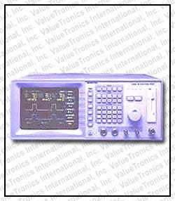
The Boonton 4400A RF Peak Power Meter and 4500A RF Peak Power Meter/Analyzer are time-domain RF power measurement instruments designed for analyzing the power-versus-time behavior of pulsed and modulated RF signals. The 4400A focuses on time-domain pulse analysis, while the 4500A extends those capabilities by adding statistical measurements (CDF, CCDF, PDF) for signals with digital modulation, multiple carriers, or complex coding techniques.
These instruments are applied to radar, pulse burst, GSM and TDMA wireless signals, broadcast TV and radio transmitter measurements, and RF amplifier linearity testing per the datasheet. The 4500A is specifically suited for signals such as CDMA, WCDMA, HDTV, DAB, and multi-carrier systems where peak-to-average power behavior must be characterized statistically. Both models support analysis of repetitive RF signals where the power-versus-time relationship must be accurately measured and recorded.
Boonton Electronics was a long-established American manufacturer of precision RF instruments, including power meters, voltmeters, modulation analyzers, and capacitance meters. The Boonton T&M business was acquired by Wireless Telecom Group, under which the 4400A and 4500A peak power meters were marketed. Boonton instruments continue to be actively used in calibration labs, broadcast facilities, defense electronics, and RF design environments, and remain a frequent request in the legacy RF used market.
The Boonton peak power instrument family covered on this datasheet consists of two models that share a common measurement architecture but address different signal analysis needs. The 4400A is a single-channel time-domain RF peak power meter focused on pulse analysis. The 4500A is a peak power meter/analyzer that adds a second measurement channel and statistical measurement capabilities (CDF, CCDF, PDF) for analyzing signals with digital modulation, multiple carriers, and complex coding techniques.
Both instruments share the same 30 MHz to 40 GHz sensor-dependent frequency range, greater than 60 dB dynamic range, 1 GHz NIST-traceable internal calibrator, 7-inch color VGA display, 1.44 MB floppy drive, and full GPIB/RS-232/parallel printer connectivity. The difference between the two models is determined by whether the application requires pulse time-domain analysis alone, or whether statistical analysis of long-running modulated signals (CDMA, WCDMA, HDTV, multi-carrier) is also needed.
Each pre-owned unit linked below is its own product page with condition-matched pricing, accessory documentation, and warranty terms specific to that listing. Review the individual product page for the exact configuration, included sensors and accessories, and current availability for the model you are evaluating.
The 4400A is positioned by the datasheet as the time-domain instrument of choice for radar, pulse bursts, GSM/TDMA wireless, broadcast TV and radio transmitter analysis, and RF amplifier linearity testing — applications where the power-versus-time relationship is the primary measurement. A single measurement channel is standard, with an optional second channel available to enable rear-panel Channel 2 and Trigger 2 inputs, a Math channel, and two Reference channels for waveform comparison and archival.
The 4500A retains every time-domain measurement capability of the 4400A and adds dual-channel statistical processing: continuous sampling at 500,000 samples per second per channel, 4,096 power bins per histogram, 32-bit bin counters, and synchronous or asynchronous measurements across the two channels. Statistical display modes include CDF, CCDF (also referred to as 1-CDF), and PDF, with X-axis ranges from 0.1% to 10% per division and percent resolution of 0.002%. Automatic statistical measurements include peak max power, average power, peak-to-average ratio, minimum power, total samples, sampling time, confidence band, dynamic range, and tolerance.
Choose the 4400A when the application is pulse and time-domain analysis of repetitive RF signals. Choose the 4500A when the application involves digitally modulated signals (CDMA, WCDMA, HDTV, DAB), multi-carrier systems, or any signal where peak-to-average ratio and statistical distribution of power levels must be characterized over long run times. See the comparison table that follows for a side-by-side view of measurement modes, sampling architecture, channel count, and statistical capabilities.
| Model | Frequency Range | Dynamic Range | Channels |
|---|---|---|---|
| 4400A | 30 MHz to 40 GHz | >60 dB (sensor dependent) | 1 (2nd channel optional) |
| 4500A | 30 MHz to 40 GHz | >60 dB (sensor dependent) | Dual-channel |
Additional differences in specifications beyond the few shown above are not listed here — see each model's full specifications below.
| Category | Specification | Value |
|---|---|---|
| Sensor Inputs | Frequency Range | 30 MHz to 40 GHz, selectable (sensor dependent) |
| Pulse Measurement Range | -40 to +20 dBm (sensor dependent) | |
| CW Measurement Range | -50 to +20 dBm (sensor dependent) | |
| Risetime (10 - 90%) | See sensor specifications | |
| Single-Shot Bandwidth | 100 kHz (based on 10 samples per pulse) | |
| Pulse Repetition Rate | 25 MHz | |
| Minimum Pulse Width | 30 ns | |
| Vertical Scale | Relative Offset Range (Log) | ±99.99 dB |
| Relative Offset Range (Linear) | 0 to 99 divisions | |
| Vertical Scale (Log) | 0.1-20 dB/div in 1-2-5 sequence | |
| Vertical Scale (Linear) | 1 nW to 50 MW in 1-2-5 sequence | |
| Time Base (Pulse Mode) | Time Base Range | 10 ns to 1 s/div |
| Time Base Accuracy | 0.01% | |
| Time Base Resolution | 200 ps | |
| Statistical Mode (4500A only) | X-Axis | 0.1, 0.2, 0.5, 1, 2, 5, 10% per division |
| Percent Offset Range | 0 - 99% (x-axis dependent) | |
| Percent Resolution | 0.002% | |
| Trigger (Pulse Mode Only) | Trigger Source | Channel 1 internal or external; or Channel 2 internal or external (optional) |
| Trigger Slope | + or - | |
| Pre-Trigger Delay (10 ns to 50 µs) | -500 µs | |
| Pre-Trigger Delay (100 µs to 1 sec) | -10 div | |
| Post-Trigger Delay (10 ns to 1 µs) | 10,000 div | |
| Post-Trigger Delay (2 µs to 50 µs) | 2 ms | |
| Post-Trigger Delay (100 µs to 1 sec) | 200 div | |
| Trigger Delay Resolution | 0.02 divisions | |
| Trigger Holdoff Range | 65 ms | |
| Trigger Holdoff Resolution | 62.5 ns | |
| Trigger View | Vertical Scale | 0.1 V to 1 V in 1-2-5 sequence |
| Relative Offset | ±3 volts | |
| Internal Trigger Range | -27 to +20 dBm (sensor dependent) | |
| External Trigger Range | ±3 volts | |
| External Trigger Input | 50 ohms, dc coupled | |
| Statistical Processing (4500A only) | Modes | CDF, 1-CDF, PDF |
| Sampling Rate | 500,000 samples per second | |
| Number of Sampling Bins | 4,096 | |
| Size of Sample Bins | 32 bits | |
| Bin Power Resolution | <0.02 dB (sensor dependent) | |
| Statistical Automatic Measurements | (4500A only) | Peak max. power, average power, peak to average ratio, minimum power, total samples, sampling time, confidence band of measurements, dynamic range, and tolerance |
| Calibration Source | Operating Modes | CW, internal or external pulse |
| Frequency | 1.024 GHz ± 0.1% | |
| Level Range | -40.0 to +20.0 dBm | |
| Resolution | 0.1 dB | |
| Output SWR (Refl. Coeff.) | 1.20, (0.091) [CW mode] | |
| Accuracy Absolute (NIST traceable, CW mode, 0 to 40°C, -30 to +20 dBm) | ±0.065 dB (1.5%) at 0 dB and 25°C, ±0.001 dB per °C | |
| Accuracy Linearity | ±0.03 dB per 5 dB | |
| Internal Pulse Period | 100 µs, 1 ms or 10 ms | |
| Internal Pulse Duty Cycle / Polarity / Connector | 10% to 90% in 10% increments; + or -; Type N | |
| Power Measurement Accuracy | Measurement Uncertainty | Total measurement uncertainty (worst case) is the sum of the calibrator uncertainty, source mismatch error, sensor calibration factor uncertainty, sensor temperature coefficient, sensor shaping, noise and drift. |
| Mismatch Uncertainty | ±2 × sensor reflection coefficient × source reflection coefficient × 100% | |
| Measurement Characteristics | Measurement Techniques (Stat Mode, 4500A only) | Continuous sampling 0.5 M samples per second |
| Measurement Techniques (Power Mode) | Random repetitive sampling system that provides pre- and post-trigger data | |
| Maximum Sample Rate | 1 MHz | |
| Memory Depth | 4 K/Channel | |
| Vertical Resolution | 0.025%, 12-bit A/D converter | |
| Waveform Averaging | 1 to 10,000 samples per data point | |
| Waveform Storage / Trigger BW | Waveform Storage | Two reference waveforms in internal non-volatile memory |
| Trigger Channel Bandwidth | > 30 MHz typical | |
| Sensor Characteristics | Power Detection Technique | Dual diode with selectable detector bandwidth |
| Log Amplifier | The logarithmic amplifier in the sensor enables the instrument to measure and analyze changes in power exceeding 60 dB in a single display range. | |
| Internal Data | Sensor calibration factors, frequency range, power range, sensor type, serial number and other sensor-dependent information are stored in EEPROM within the peak power sensor. | |
| Sensor Cable | Detachable from both the sensor and instrument. Standard cable length is 5 feet. Other cable lengths are 10 feet, 20 feet, 25 feet and 50 feet. | |
| Rear Panel Connections | External Calibrator Pulse Input | External TTL-level signal to control the pulse rate and duty cycle of the calibrator output (50 ohm input impedance) |
Please review the Manufacturer's Data Sheet to verify published specifications. Feedback on this webpage is always welcome — please reach out to your Test Architect at any time for questions or concerns. Thank you, we truly appreciate you being our customer.
Model No
Boonton
Condition
Used
Manufacturer
Boonton

30+ Years in Business
Secure Payments
Sell Test Equipments
Knowledgeable Staff
On-site Lab
30+ Years in Business
Secure Payments
Sell Test Equipments
Knowledgeable Staff
On-site Lab
Request A Quote
 Chat Live
 Contact Us
 sales@valuetronics.com