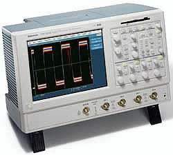
The Tektronix TDS5000 Series is a family of digital phosphor oscilloscopes delivering up to 1 GHz bandwidth, 5 GS/s real-time sample rate, up to 8 MB record length, and a 100,000 waveforms-per-second maximum capture rate in a compact bench-top package. Digital phosphor oscilloscopes display, store, and analyze complex signals in real time using three dimensions of signal information — amplitude, time, and the distribution of amplitude over time — providing insight into signal behavior that a conventional display cannot. The series pairs that acquisition performance with an industry-leading suite of advanced triggers, an intuitive user interface, and an open Microsoft Windows platform.
The TDS5000 Series supports a broad range of design and test work. Listed applications include digital design and debug, investigation of transient phenomena, power measurements, video design and debug, DVD analysis, disk drive analysis, jitter and timing analysis, and spectral analysis. The series is also applied to automotive electronics design and debug, manufacturing test and quality control, electro-mechanical design and analysis, bio-medical product development, and industrial control.
ValueTronics has supplied test and measurement equipment since 1992 from its own 20,000-square-foot secure warehouse at 1675 Cambridge Drive in Elgin, Illinois, where we stock and hold our inventory on hand. Pre-owned instruments are inspected and functionally verified in-house by our technicians before they ship, while new units leave factory-sealed exactly as received. That combination of held inventory and hands-on verification means the oscilloscope you order is ready to ship and backed by people who know the product.
The TDS5000 Series comprises three digital phosphor oscilloscope models that share the same DPX acquisition engine, open Windows platform, and advanced trigger suite while differing in bandwidth and channel count. All three deliver a 5 GS/s maximum single-channel real-time sample rate, up to 8 MB record length with Option 2M, and a 100,000 wfms/s maximum waveform capture rate. The models differ in analog bandwidth (500 MHz or 1 GHz) and in the number of input channels (2 or 4).
Because each model is delivered as a self-contained oscilloscope-and-PC unit, they carry the same connectivity, display, and analysis software. The choice between models is driven by the bandwidth and channel count an application requires rather than by differences in the user interface or measurement toolset.
Each model below is its own dedicated product page with condition-matched pricing. Select the pre-owned listing for the specific model and channel count your application requires; the family-level specifications described here apply across the series, while the per-model differences are summarized in the comparison table.
The three models separate along two axes. The TDS5052 provides 500 MHz bandwidth on 2 channels, the TDS5054 provides 500 MHz bandwidth on 4 channels, and the TDS5104 provides 1 GHz bandwidth on 4 channels. The 500 MHz models have a typical calculated rise time of 800 ps at 5 mV/div, while the 1 GHz TDS5104 has a 400 ps typical rise time. On the 4-channel models the maximum real-time sample rate across three or four channels is 1.25 GS/s, whereas the 2-channel TDS5052 reaches 2.5 GS/s on its two channels.
Channel count also affects triggering and outputs. Logic qualification on the runt and window triggers is available on the 4-channel models only, and the buffered analog signal output is provided on 4-channel models only. The state trigger clocks channels 1, 2, and 3 on an edge of channel 4, except on the 2-channel TDS5052, where it is clocked on channel 2. See the comparison table for the full per-model breakdown.
| Model | Bandwidth | Analog Channels | Calculated Rise Time |
|---|---|---|---|
| TDS5104 | 1 GHz | 4 | 400 ps |
| TDS5052 | 500 MHz | 2 | 800 ps |
| TDS5054 | 500 MHz | 4 | 800 ps |
Additional differences in specifications beyond the few shown above are not listed here — see each model's full specifications below.
| Specification | Value |
|---|---|
| Vertical System | |
| Input Channels | 4 |
| Analog Bandwidth (–3 dB), 5 mV/div to 1 V/div | 1 GHz |
| Calculated Rise Time, 5 mV/div (typical) | 400 ps |
| Hardware Bandwidth Limits | 150 MHz or 20 MHz |
| Input Coupling | AC, DC, GND |
| Input Impedance | 1 MΩ ± 1% or 50 Ω ± 1% |
| Input Sensitivity, 1 MΩ | 1 mV/div to 10 V/div |
| Input Sensitivity, 50 Ω | 1 mV/div to 1 V/div |
| Vertical Resolution | 8-bits (> 11-bits w/ averaging) |
| Max Input Voltage, 1 MΩ | ± 150 V CAT I, derate at 20 dB/decade to 9 VRMS above 200 kHz |
| Max Input Voltage, 50 Ω | 5 VRMS with peaks < ± 30 V |
| DC Gain Accuracy | 1.5% with offset set to 0 V |
| Offset Range, 1 MΩ | 1 mV/div to 99.5 mV/div: ± 1 V; 100 mV/div to 1 V/div: ± 10 V; 1.01 V/div to 10 V/div: ± 100 V |
| Offset Range, 50 Ω | 1 mV to 50 mV/div: ± 0.5 V; 50.5 mV to 99.5 mV/div: ± 0.25 V; 100 mV to 500 mV/div: ± 5 V; 505 mV to 1 V/div: ± 2.5 V |
| Channel-to-channel Isolation (any two channels at equal vertical scale) | ≥ 100:1 at ≤ 100 MHz and ≥ 30:1 at > 100 MHz up to the rated bandwidth |
| Timebase System | |
| Timebase Range | 200 ps/div to 40 s/div |
| Timebase Delay Time Range | 16 ns to 250 s |
| Channel-to-channel Deskew Range | ± 25 ns |
| Delta Time Measurement Accuracy | ± (0.30 sample interval) + (15 ppm × reading) |
| Trigger Jitter (RMS) | 8 psRMS (typical) |
| Long Term Sample Rate and Delay Time Accuracy | ± 15 ppm over ≥ 1 ms interval |
| Acquisition System | |
| Real-time Sample Rate, 1 Channel (max) | 5 GS/s |
| Real-time Sample Rate, 2 Channels (max) | 2.5 GS/s |
| Real-time Sample Rate, 3-4 Channels (max) | 1.25 GS/s |
| Equivalent Time Sample Rate (max) | 250 GS/s |
| Maximum Record Length, Standard Memory | 400 k (1 ch); 200 k (2 ch); 100 k (4 ch) |
| Maximum Record Length, Opt. 1M | 2 M (1 ch); 1 M (2 ch); 500 k (4 ch) |
| Maximum Record Length, Opt. 2M | 8 M (1 ch); 4 M (2 ch); 2 M (4 ch) |
| Time Resolution (single shot) | 200 ps (5 GS/s) |
| Max Duration with Standard Memory | 80 µs |
| Max Duration with Opt. 1M | 400 µs |
| Max Duration with Opt. 2M | 1.6 ms |
| Acquisition Modes | |
| Maximum FastAcq Waveform Capture Rate | 100,000 wfms/s |
| Peak Detect, Minimum Pulse Width | < 1 ns |
| Averaging | From 2 to 10,000 waveforms included in average |
| Envelope | From 2 to 2 × 10⁹ waveforms included in min-max envelope |
| Hi-Res | Real-time boxcar averaging reduces random noise and increases resolution |
| Trigger System | |
| Sensitivity, Internal DC Coupled | 0.35 div DC to 50 MHz increasing to 1 div at 1 GHz |
| Sensitivity, External (auxiliary input) | 400 mV from DC to 50 MHz increasing to 750 mV at 100 MHz |
| Main Trigger Modes | Auto, Normal and Single |
| Trigger Level Range, Internal | ± 10 divisions from center of screen |
| Trigger Level Range, External (auxiliary in) | ± 8 V |
| Trigger Level Range, Line | Fixed at 0 V |
| Trigger Coupling | DC, AC (attenuate < 60 Hz), HF reject (attenuate > 30 kHz), LF reject (attenuates < 80 kHz), noise reject (reduce sensitivity) |
| Trigger Holdoff Range | 250 ns minimum to 12 s maximum |
| Trigger Delay by Time | 16 ns to 250 seconds |
| Trigger Delay by Events | 1 to 10,000,000 Events |
| Display Characteristics | |
| Display Type | Liquid crystal active-matrix color display |
| Display Size | 211.2 mm (W) × 158.4 mm (H), 264 mm (10.4 in) diagonal |
| Display Resolution | 640 horizontal × 480 vertical pixels |
| Computer System and Peripherals | |
| CPU | Intel Celeron Processor, 800 MHz |
| PC System Memory | 128 MB |
| Hard Disk Drive | > 10 GB capacity |
| Floppy Disk Drive | Front panel 3.5 in, 1.44 MB capacity |
| CD-ROM Drive | Side panel CD-ROM drive |
| Input/Output Ports | |
| Auxiliary Input | Front panel BNC; trigger level adjustable + 8 V to –8 V; maximum input voltage ± 20 V |
| Probe Compensator Output | Front panel pins; 1 V ± 1% into ≥ 10 kΩ load, 1 kHz ± 5% |
| Analog Signal Output Amplitude (4 channel models only) | 20 mV/div ± 20% into 1 MΩ load, 10 mV/div ± 20% into 50 Ω load (buffered Channel 3) |
| Analog Signal Output Bandwidth, Typical (4 channel models only) | 100 MHz into a 50 Ω load |
| External Reference In | Rear-panel BNC; 9.8 MHz to 10.2 MHz |
| Parallel Port | IEEE 1284, DB-25 connector |
| LAN Port | RJ-45 connector, supports 10Base-T and 100Base-T |
| Serial Port | DB-9 COM1 port |
Important: Maximum input voltage (1 MΩ): ±150 V CAT I, derated at 20 dB/decade to 9 VRMS above 200 kHz. Maximum input voltage (50 Ω): 5 VRMS with peaks < ±30 V. Auxiliary input maximum: ±20 V.
Important: The TDS5104 ships with no probes included; the TDS5052 includes two P5050 500 MHz 10x passive probes and the TDS5054 includes four P5050 500 MHz 10x passive probes. Probes for the TDS5104 must be ordered separately (see Probe Options).
Important: A keyboard is not included in the standard delivery; the USB keyboard must be ordered separately (Tektronix order 119-6633-00 / 119-6297-00).
Important: Acquisition memory upgrades (equivalent to Opt. 1M and 2M) and software upgrades (equivalent to Opt. 2A, J1 and J2) can be ordered after initial purchase via the TDS5UP upgrade kit; users can install upgrades without opening the instrument case or requiring on-site service.
Recommended pairing: use the Tektronix TLA600 logic analyzer with Integrated View (iView) for a time-correlated view of analog and digital signals.
This pre-owned unit is inspected and functionally verified in-house before it ships and is backed by our pre-owned warranty. To confirm its exact condition, firmware revision, installed options, or included accessories for your application before ordering, contact our Test Architects.
ValueTronics supplies both new and used test and measurement equipment. New units ship factory-sealed, exactly as received from the manufacturer; every used unit is inspected and functionally verified in-house at our 20,000 sq ft secure facility in Elgin, Illinois before it ships. Our Test Architects can help you select the condition, calibration, and configuration that fit your application.
Please review the Manufacturer's Data Sheet to verify published specifications. Feedback on this webpage is always welcome — please reach out to your Test Architect at any time for questions or concerns. Thank you, we truly appreciate you being our customer.
Model No
Tektronix
Condition
Pre-Owned
Manufacturer
Tektronix
Osc_ch
4
Osc_freq
1 GHz
Osc_r
1 MΩ or 50 Ω
Osc_sampl
5 GS/s
2A
Advanced analysis , Equation editor , Spectral FFT and histograms
2M
8 Msamples max (1 ch)
J3E
Jitter and timing analysis software essentials

30+ Years in Business
Secure Payments
Sell Test Equipments
Knowledgeable Staff
On-site Lab
30+ Years in Business
Secure Payments
Sell Test Equipments
Knowledgeable Staff
On-site Lab
Request A Quote
 Chat Live
 Contact Us
 sales@valuetronics.com