🎓 Request a Quote To Get An EDU Discount
Couldn't load pickup availability
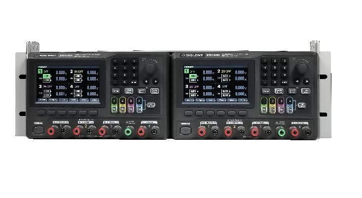
In summary, the Siglent SPD4306X is a four-channel programmable linear DC power supply delivering up to 400 W total output. Channel 1 and Channel 2 are full programmable channels at up to 30 V and 6 A each, with independent or parallel / series tracking modes. Channel 3 provides a 5 V fixed-range auxiliary output up to 3 A, and Channel 4 provides a low-power auxiliary output up to 1 A. Per the datasheet, the SPD4306X provides 1 mV / 1 mA programming resolution, overvoltage / overcurrent / overtemperature protection on every channel, list / wave / delay sequencing on Channels 1-3, and a 4.3 inch TFT display.
The SPD4306X is used for multi-rail DUT bring-up — powering a circuit's analog, digital, and auxiliary rails simultaneously from a single instrument — and for automated characterization sweeps where programmability over LAN, USB, or GPIB allows the supply to be stepped through a voltage or current profile by a test script. Linear regulation makes the SPD4306X a low-noise source, well suited to general-purpose multi-rail benches needing 30 V and meaningful current. Per the datasheet, programming resolution is 1 mV / 1 mA, output noise is typically 350 µV rms (CH1 / CH2), and load and line regulation are each under 0.01% + 3 mV. Standard channel-tracking modes include independent, parallel (sum of currents at single voltage), and series (sum of voltages at single current).
Linear DC power supplies regulate the output by dissipating excess voltage as heat in a series-pass element. The result is very low output ripple and very low high-frequency switching noise — valuable for analog, RF, audio, sensor, and medical circuit work where supply-induced noise could mask the measurement of interest. The trade-off is lower efficiency and a larger, heavier chassis at comparable output power versus a switching supply. The SPD4306X is a linear supply, so it is the right choice when the customer needs clean DC for noise-sensitive measurement; it is not the right choice when the application is high-power motor or industrial loads, where a switching architecture would be more appropriate.
Per the manufacturer datasheet, the standard ship kit includes: a Quick Start guide, a region-appropriate AC power cord, a USB cable, and a set of binding-post test leads. Optional accessories include a rack-mount kit, an external trigger / digital I/O cable, a USB-GPIB adapter for IEEE-488 control, and SCPI / IVI driver downloads from the manufacturer.
| Architecture | Linear regulation, 4-channel programmable |
|---|---|
| Output channels | 4 channels: CH1/CH2 each 0-30 V / 0-6 A; CH3 0-5 V / 0-3 A; CH4 0-30 V / 0-1 A |
| Total output power | 400 W maximum |
| Programming resolution | 1 mV / 1 mA on all programmable channels |
| Readback resolution | 1 mV / 1 mA |
| Output isolation | Channels are independently isolated; series / parallel tracking supported between CH1 and CH2 |
| Load regulation, voltage / current | ≤ 0.01% + 3 mV / ≤ 0.01% + 3 mA (CV / CC) |
|---|---|
| Line regulation, voltage / current | ≤ 0.01% + 3 mV / ≤ 0.01% + 3 mA |
| Programming accuracy, voltage / current | ≤ 0.03% + 10 mV / ≤ 0.1% + 5 mA |
| Readback accuracy, voltage / current | ≤ 0.03% + 10 mV / ≤ 0.1% + 5 mA |
| Output ripple and noise (rms) | 350 µV rms typ. (CH1/CH2) |
| Output ripple and noise (peak-peak) | ≤ 2 mV typical (CH1 / CH2) |
| Recovery time after step load change | < 100 µs, 50% to 100% load step |
| Temperature coefficient | ≤ 50 ppm/°C (voltage), ≤ 100 ppm/°C (current) |
| Overvoltage protection (OVP) | Per channel, settable across full range |
|---|---|
| Overcurrent protection (OCP) | Per channel, settable across full range |
| Overtemperature protection (OTP) | Internal sensor, automatic output disable |
| Front-panel lock | Yes, prevents unintended adjustment |
| List / Wave / Delay sequencing | Yes, on Channels 1-3; multi-step voltage / current profiles |
| Display | 4.3 inch TFT, multi-window per channel |
| Internal resistance setting | Yes, programmable on CH1 / CH2 for battery-emulation work |
| Front-panel controls | Per-channel encoder, multi-window display, numeric keypad |
|---|---|
| USB / LAN | USB Host + USB Device / 10/100 Base, RJ-45 |
| Digital I/O / external trigger | Available via rear-panel connector |
| Remote protocols | SCPI / LabVIEW / IVI; USB-TMC, VXI-11, Socket, Telnet; GPIB via USB-GPIB adapter |
| Dimensions (W×H×D, approx.) | 230 × 142 × 290 mm |
| Weight (net, approx.) | approx. 7.6 kg (16.8 lb) |
| AC source | 100-240 V, 50/60 Hz; auto-sensing |
| Operating temperature / humidity | 0 to 40 °C; ≤ 80% RH at 40 °C, non-condensing |
| Safety / EMC / RoHS | EN 61010-1; EN 61326-1; 2011/65/EU |
Channel 3 is intended as a fixed-range 5 V auxiliary up to 3 A and is appropriate for powering a logic rail; Channel 4 provides a small auxiliary output up to 1 A for bias or pull-up rails. List / Wave / Delay sequencing is supported on Channels 1-3; Channel 4 is intended as a static auxiliary. Confirm channel assignments for the specific test application.
This webpage was written by a human with an A.I. "Intern", which may contain errors. Please review the Manufacturer's Data Sheet to verify published specifications. Feedback on this webpage is always welcome — please reach out to your Test Architect at any time for questions or concerns. Thank you, we truly appreciate you being our customer.
Model No
SPD4306X
Condition
New
Manufacturer
Siglent
Current
6 A
Voltage
30 V
Power
400 W

30+ Years in Business
Secure Payments
Sell Test Equipments
Knowledgeable Staff
On-site Lab
30+ Years in Business
Secure Payments
Sell Test Equipments
Knowledgeable Staff
On-site Lab
Request A Quote
 Chat Live
 Contact Us
 sales@valuetronics.com
