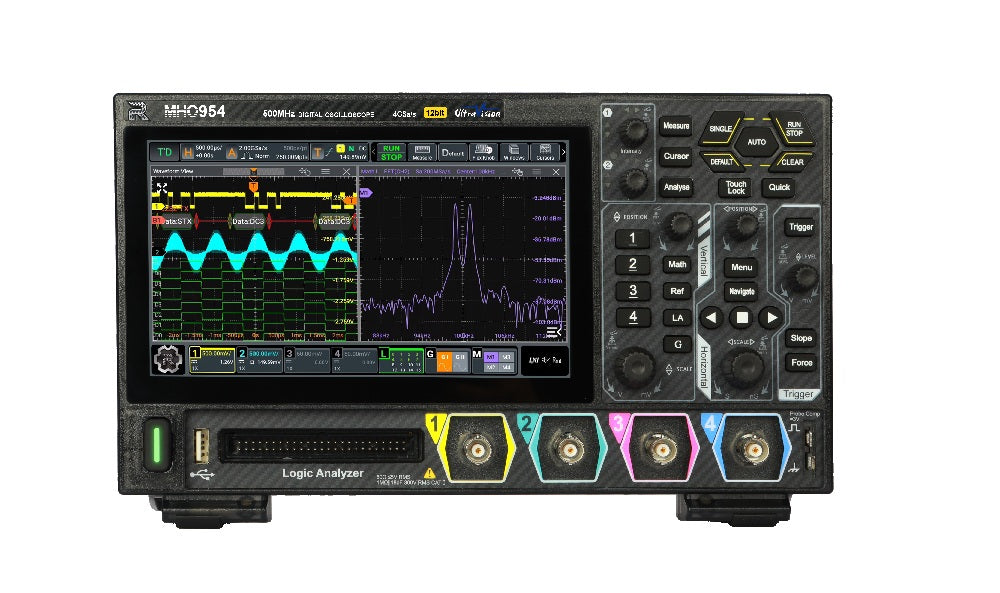
In summary, the Rigol MHO954 is a 4-channel mixed-signal digital oscilloscope built around a 12-bit ADC, 500 MHz of analog bandwidth, and a 4 GSa/s real-time sample rate. With 100 Mpts of standard memory (expandable to 500 Mpts), a 1,000,000 wfms/s fast-record capture rate, and a 7-inch capacitive multi-touch interface, it targets embedded design, power-electronics debug, education, and general-purpose bench work.
The MHO954 is used for time-domain analysis of analog and mixed-signal electronics — debugging microcontroller buses, characterizing switching-supply ripple, validating sensor outputs, and analyzing serial protocols such as I2C, SPI, UART, CAN, and LIN. The 12-bit vertical path resolves details that 8-bit instruments cannot, which is particularly valuable for power-rail ripple measurements and small-signal work riding on larger DC offsets.
Embedded developers, hardware engineers, educators, and lab technicians who need a 4-channel scope with protocol decode, deep memory, and a usable touch UI at an accessible price point. The optional 2-channel AFG and Bode plot turn the MHO954 into a self-contained loop-response and stimulus-response bench in a single chassis.
The MHO954 provides 500 MHz of analog bandwidth (50 Ω path) with a typical 10%–90% rising time of 700 ps and an effective number of bits (ENOB) of 8.1 at 10 MHz, 100 mV/div. Trigger holdoff spans 8 ns to 10 s, and the trigger sensitivity is 0.5 div (≥50 mV/div). Time-base accuracy is ±1.5 ppm ±1 ppm/year. Standard memory is 100 Mpts single-channel; the MHO900-RLU-05 option extends this 5× to 500 Mpts.
The MHO954 conforms to EMC DIRECTIVE 2014/30/EU and IEC 61326-1:2013 Group 1 Class A, with safety to EN 61010-1:2019, IEC 61010-1:2016, UL 61010-1:2012 R7, and CAN/CSA-22.2 No. 61010-1-12:2017. It supports IEEE 488.2-compliant SCPI for programmatic control over LAN (LXI-C), USB, and supports a Web Control interface for browser-based remote operation.
| Item | Notes |
|---|---|
| Power Adapter | Conforming to the standard of the destination country |
| Ground Cable | — |
| USB Cable | — |
| 4 × RP3500A Passive Probes (500 MHz) | Standard configuration |
| Parameter | Value |
|---|---|
| Max. Analog Bandwidth (50 Ω, -3 dB) | 500 MHz (single-channel & half-channel); 400 MHz (all-channel) |
| Max. Analog Bandwidth (1 MΩ, -3 dB) | 500 MHz (single-channel & half-channel); 400 MHz (all-channel) |
| Calculated Rising Time under 50 Ω (10%–90%, typical) | 700 ps |
| Effective Number of Bits (ENOB, typical) | 8.1 |
| No. of Analog Channels | 4 |
| Digital Channels | 16 (with optional PLA2216 logic analyzer probe) |
| Max. Real-time Sample Rate | 4 GSa/s single-channel; 2 GSa/s half-channel; 1 GSa/s all-channel |
| Standard Probe | RP3500A (500 MHz, 10:1) × 4 |
| Parameter | Value |
|---|---|
| Sampling Mode | Real-time Sampling |
| Max. Real-time Sample Rate | 4 GSa/s (single-channel); 2 GSa/s (half-channel); 1 GSa/s (all-channel) |
| Max. Memory Depth (Standard) | 100 Mpts (single-channel); 50 Mpts (half-channel); 25 Mpts (all-channel) |
| Max. Memory Depth (Optional) | With 500 Mpts memory option: 500 / 250 / 125 Mpts |
| Input Impedance | 50 Ω ± 1%, 1 MΩ ± 1% |
| Max. Waveform Capture Rate | 30,000 wfms/s (Vector mode); 1,000,000 wfms/s (fast recording mode) |
| Vertical Resolution | 12-bit (4,096 digitalizing levels); up to 16-bit in High Resolution mode |
| Hardware Waveform Recording | Max. 500,000 frames |
| Peak Detection | Captures 500 ps glitches |
| Display | 7-inch capacitive multi-touch screen, 1024×600 (16:9) |
| Digital Phosphor Display | 256-level intensity grading |
| Communication Interfaces | HDMI, LAN (100M, LXI-C), USB2.0 Host & Device |
| Programming | Standard SCPI instruction sets, IEEE488.2 |
| Processor | Cortex-A72 up to 1.8 GHz, 6-core |
| System Memory / Internal Storage | 4 GB RAM / 32 GB non-volatile |
| Operating System | Android |
| Dimensions | 265.35 mm (W) × 161.75 mm (H) × 77.38 mm (D) |
| Weight | Approximately 1.6 kg (package excluded) |
| Power | Type-C interface; DC 20 V, 5 A; 70 W |
| Operating Temperature | 0°C to +50°C |
| Warranty | Three years for the mainframe, excluding the probes and accessories. |
| Recommended Calibration Interval | 18 months |
| Parameter | Value |
|---|---|
| Input Coupling | DC, AC, or GND |
| Input Capacitance | 18 pF ± 3 pF |
| Vertical Sensitivity | 50 Ω: 200 µV/div to 1 V/div; 1 MΩ: 1 mV/div to 10 V/div |
| Max. Input Voltage | 1 MΩ: CAT I 300 Vrms, 400 Vpk (DC + Vpeak); 50 Ω: 5 Vrms |
| Dynamic Range | ±4 div |
| Bandwidth Limit (Typical) | 20 MHz, 250 MHz, FULL |
| DC Gain Accuracy | ±1% (≥5 mV/div); ±2% (<5 mV/div) |
| Channel-to-Channel Isolation | ≥100:1 (DC to full bandwidth) |
| ESD Tolerance | ±8 kV |
| Parameter | Value |
|---|---|
| Number of Channels | 16 input channels (D0 to D15; groups D0–D7, D8–D15) |
| Threshold Range | ±15.0 V, in 10 mV step |
| Threshold Accuracy | ±(100.00 mV + 3% of threshold setting) |
| Max. Input Voltage | ±40 V peak CAT I; transient overvoltage 800 Vpk |
| Minimum Voltage Swing | 500 mVpp |
| Input Impedance / Probe Load | About 101 kΩ / ≈8 pF |
| Min. Detectable Pulse Width | 5 ns |
| Maximum Input Frequency | 200 MHz |
| Parameter | Value |
|---|---|
| Range of Time Base | 500 ps/div to 500 s/div; fine adjustment supported |
| Time Base Resolution | 100 ps |
| Time Base Accuracy | ±1.5 ppm ± 1 ppm/year |
| Pre-trigger / Post-trigger | -5 div / 1 s or 100 div, whichever is greater |
| Channel-to-Channel Skew Correction | Range ±100 ns, accuracy ±1 ps |
| Horizontal Modes | YT, XY, SCAN (≥200 ms/div), ROLL (≥50 ms/div) |
| Parameter | Value |
|---|---|
| Trigger Source | Analog channels (CH1–CH4), digital channels (D0–D15) |
| Trigger Mode | Auto, Normal, Single |
| Trigger Coupling | DC, AC, HF Reject (200 kHz ±20%), LF Reject (180 kHz ±20%), Noise Reject |
| Holdoff Range | 8 ns to 10 s |
| Trigger Sensitivity | Internal trigger: 0.5 div, ≥50 mV/div; 0.7 div with noise rejection |
| Trigger Types (Standard) | Edge, Pulse, Slope, Video, Pattern, Duration, Timeout, Runt, Window, Delay, Setup/Hold, Nth Edge, RS232, I2C, SPI, CAN, LIN |
| Trigger Types (Option) | FlexRay, I2S, MIL-STD-1553 |
| Parameter | Value |
|---|---|
| Acquisition Modes | Normal, Peak Detection (500 ps glitches), Average (2 to 65536), High Resolution (14-bit, 16-bit) |
| Waveform Recording | Up to 500,000 segments |
| PassFail | User-defined mask with success/fail/total counts and event actions |
| Histogram | Horizontal, vertical, measure types |
| Color Grade | 256-level color scale; temperature and intensity themes |
| Auto Measurements | 41 measurements; up to 14 displayed at once; statistics include Current, Average, Max, Min, Std Dev, Count |
| Math Functions | 4 simultaneous; A+B, A-B, A×B, A/B, FFT, logic ops, Intg, Diff, Sqrt, Lg, Ln, Exp, Abs, AX+B, LowPass, HighPass, BandPass, BandStop |
| FFT | Max. 1 Mpts record length; Rectangular, Blackman-Harris, Hanning, Hamming, Flattop, Triangle windows |
| Parameter | Value |
|---|---|
| Simultaneous Decodes | Four protocol types at the same time |
| Standard | Parallel, RS232/UART (up to 20 Mb/s), I2C, SPI, LIN (up to 20 Mb/s), CAN (up to 5 Mb/s) |
| Optional | CAN-FD (up to 10 Mb/s), FlexRay (up to 10 Mb/s), I2S, MIL-STD-1553B |
| Parameter | Value |
|---|---|
| Bode Plot Sweep | Start 10 Hz to 3 MHz; Stop 100 Hz to 30 MHz; 10 to 100 points/decade; output 20 mV to 10 V (requires AFG option) |
| Digital Voltmeter | DC, AC+DC rms, AC rms; ACV/DCV: 3 digits; limits beeper |
| Frequency Counter | Frequency, period, totalizer; 3–6 digit user-defined resolution; 48-bit totalizer |
Optional 2-channel AFG with 1 GSa/s sample rate and 16-bit vertical resolution. Available in two performance tiers (MHO900-AFG50: 50 MHz; MHO900-AFG100: 100 MHz). Output waveforms include Sine, Square, Ramp, DC, Noise, Arbitrary, and built-in Sinc, Exp.Rise, Exp.Fall, ECG1, Gauss, Lorentz, and Haversine. AM/FM/PM modulation supported. Sine flatness ±0.2 dB below 10 MHz; THD <0.1% (10 Hz to 20 kHz, 1 Vpp). Frequency accuracy ±1.5 ppm ±1 ppm/year.
| Parameter | Value |
|---|---|
| EMC | Compliant with EMC DIRECTIVE 2014/30/EU; IEC 61326-1:2013 Group 1 Class A |
| Safety | EN 61010-1:2019, IEC 61010-1:2016, UL 61010-1:2012 R7, CAN/CSA-22.2 No. 61010-1-12:2017 |
| Operating Humidity | ≤90% RH below +30°C; ≤75% RH +30°C to +40°C; ≤45% RH +40°C to +50°C |
| Operating Altitude | Below 3,000 m |
| Vibration / Shock | Meets MIL-PRF-28800F class 3 random / 30 g half-sine, 11 ms duration |
| Order No. | Description |
|---|---|
| MHO900-RLU-05 | 500 Mpts Memory Depth Option |
| MHO900-BWU03T05 | 350 MHz to 500 MHz Bandwidth Upgrade |
| MHO900-BWU03T08 | 350 MHz to 800 MHz Bandwidth Upgrade |
| MHO900-BWU05T08 | 500 MHz to 800 MHz Bandwidth Upgrade |
| MHO900-AFG50 | 50 MHz Function/Arbitrary Waveform Generator (Bode plot supported) |
| MHO900-AFG100 | 100 MHz Function/Arbitrary Waveform Generator (Bode plot supported) |
| MHO900-AUDIOA | Audio Serial Bus Trigger and Analysis |
| MHO900-AUTOA | CAN Serial Bus Analysis with Flexible Data Rate |
| MHO900-FlexA | FlexRay Serial Bus Trigger and Analysis |
| MHO900-AEROA | MIL-STD-1553 Bus Trigger and Analysis |
| MHO900-BND | Function and Application Bundle (AFG100, AUDIOA, AUTOA, FlexA, AEROA) |
| PLA2216 | 16-channel Logic Analyzer Probe |
| BAG-800 | Portable Instrument Bag |
This webpage was written by a human with an A.I. "Intern", which may contain errors. Please review the Manufacturers Data Sheet to verify published specifications. Feedback on this webpage is always welcome, please reach out to your Test Architect at any time for questions or concerns. Thank you, we truly appreciate you being our customer.
Model No
MHO954
Condition
New
Manufacturer
Rigol
Channels
4
Frequency
800 MHz
Sampling rate
4 GS/s

30+ Years in Business
Secure Payments
Sell Test Equipments
Knowledgeable Staff
On-site Lab
30+ Years in Business
Secure Payments
Sell Test Equipments
Knowledgeable Staff
On-site Lab
Request A Quote
 Chat Live
 Contact Us
 sales@valuetronics.com