The GW Instek MFG-2000 Series is a family of multi-channel function generators that combines up to five distinct signal sources in a single benchtop instrument. Depending on model, the series integrates one or two equivalent-performance arbitrary function generator channels, an RF signal generator, a 25 MHz pulse generator, and a 20 W audio-range power amplifier. The ten models in the series range from a basic single-channel arbitrary function generator with pulse generator up through fully loaded five-channel configurations that pair dual 60 MHz AFG channels with a 320 MHz RF signal generator and the power amplifier.
The series is positioned for educational and industrial applications that benefit from consolidating multiple signal sources at one bench position. Stated applications include dual-channel correlated waveform generation, IQ modulation signal generation, low-frequency vibration simulation, automotive sensor simulation, AM/FM broadcast signal simulation, PWM motor and fan control signal generation, pulse-synchronized signal generation, pulse-noise generation, and audio circuit and speaker testing. The combination of an AFG channel, an RF channel, a pulse generator, and a power amplifier in one chassis supports use in scientific research, education, R&D, and production quality control.
GW Instek is the test and measurement brand of Good Will Instrument Co., Ltd., a Taiwan-based instrument manufacturer founded in 1975 and headquartered in New Taipei City. The company has operated continuously under the GW Instek brand and has not undergone a major corporate acquisition or rebrand affecting the product line.
The MFG-2000 Series is structured as ten models that share a common chassis, display, and arbitrary-waveform engine but differ in which functional channels are populated. Every model includes one AFG channel and a 25 MHz pulse generator. From there, the configurations branch on four independent axes: AFG channel count (one or two), AFG channel bandwidth (10, 20, 30, or 60 MHz), the presence and bandwidth of an RF signal generator channel (none, 160 MHz, or 320 MHz), and the presence of the 20 W power amplifier.
Within the family, model numbers in the MFG-21XX range are single-channel AFG models and MFG-22XX numbers are dual-channel AFG models. Model suffixes encode the additional channels: M indicates the modulation/sweep/burst/frequency-counter feature set, MF indicates a 160 MHz RF channel, MR indicates a 320 MHz RF channel, and the A suffix indicates the power amplifier is installed. LAN is included only on MFG-22XX models.
Each model below is listed as its own product page with new-matched pricing. Confirm that the suffix matches the channel set you need before ordering, since the suffix difference is the difference between single-channel and dual-channel AFG, between no RF channel and a 320 MHz RF channel, and between a unit with or without the power amplifier installed.
The four entry models — MFG-2110, MFG-2120, MFG-2120MA, and MFG-2130M — are all single-channel AFGs paired with the pulse generator. They differ in AFG bandwidth (10 MHz, 20 MHz, 20 MHz with power amplifier, and 30 MHz respectively) and in whether modulation and the power amplifier are present. The MFG-2160MF and MFG-2160MR add a 60 MHz AFG channel and an RF signal generator at 160 MHz and 320 MHz respectively; these are the single-channel-AFG models intended for applications that need both baseband and RF stimulus from one instrument.
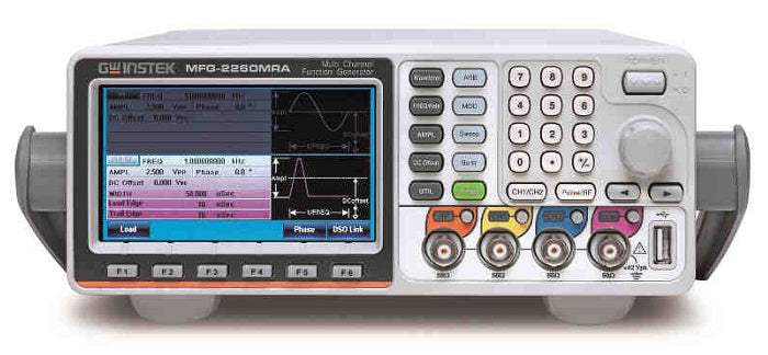
The MFG-22XX dual-channel models add a second equivalent-performance AFG channel and add LAN connectivity. The MFG-2230M provides dual 30 MHz AFG channels; the MFG-2260M provides dual 60 MHz AFG channels; the MFG-2260MFA adds the 160 MHz RF channel and the 20 W power amplifier to dual 60 MHz AFG channels; and the MFG-2260MRA is the top configuration, with dual 60 MHz AFG channels, a 320 MHz RF channel, and the power amplifier. The comparison table below lists the channel inventory for each model side by side so the per-axis differences are explicit.
| Model | CH1 Frequency | CH2 Frequency | RF Generator |
|---|---|---|---|
| MFG-2260MRA | 60 MHz | 60 MHz | 320 MHz |
| MFG-2110 | 10 MHz | — | — |
| MFG-2120 | 20 MHz | — | — |
| MFG-2120MA | 20 MHz | — | — |
Additional differences in specifications beyond the few shown above are not listed here — see each model's full specifications below.
| CH1 / CH2 Specifications (Function With ARB) | |
|---|---|
| Standard Waveforms | Sine, Square, Ramp, Pulse, Noise |
| Arb Function | Built-in |
| Sample Rate | 200 MSa/s |
| Repetition Rate | 100 MHz |
| Waveform Length | 16k points |
| Amplitude Resolution | 14 bits |
| Non-volatile Memory | 10 sets, 16k points each |
| User-defined Output Section | From point 2 ~ 16384 (user-defined) |
| User-defined Output Marker Section | From point 2 ~ 16384 (user-defined) |
| Output Mode | 1~1,048,575 cycles or infinite mode |
| Frequency Range | Sine: 60 MHz (max); Square: 25 MHz (max); Triangle, Ramp: 1 MHz |
| Frequency Resolution | 1 µHz |
| Accuracy Stability | ±20 ppm |
| Aging | ±1 ppm, per 1 year |
| Tolerance | ≤ 1 µHz |
| Amplitude Range | 1 mVpp to 10 Vpp (into 50Ω); 2 mVpp to 20 Vpp (open-circuit) |
| Amplitude Accuracy | ±2% of setting ±1 mVpp (at 1 kHz/into 50Ω without DC offset) |
| Amplitude Resolution | 0.1 mV or 4 digits |
| Flatness | ±1% (0.1 dB) ≤1 MHz; ±3% (0.3 dB) ≤50 MHz; ±10% (0.9 dB) ≤160 MHz; ±30% (3 dB) ≤320 MHz (sinewave relative to 1 kHz/into 50Ω) |
| Amplitude Units | Vpp, Vrms, dBm |
| DC Offset Range | ±5 Vpk AC+DC (into 50Ω); ±10 Vpk AC+DC (open circuit) |
| DC Offset Accuracy | 1% of setting + 5 mV + 0.5% of amplitude |
| Output Impedance | 50Ω typical (fixed); > 10 MΩ (output disabled) |
| Output Protection | Short-circuit protected; Overload relay automatically disables main output |
| Output Ground Isolation | 42 Vpk max |
| Sync Output | TTL-compatible into >1 kΩ; 50Ω standard; 42 Vpk max isolation |
| Sine Wave Harmonic Distortion | −60 dBc DC~200 kHz; −55 dBc 200 kHz~1 MHz; −45 dBc 1 MHz~10 MHz; −30 dBc 10 MHz~320 MHz (Ampl > 0.1 Vpp) |
| Sine Wave THD | < 0.1% (Ampl > 1 Vpp) DC~100 kHz |
| Square Wave Rise/Fall Time | < 15 ns |
| Square Wave Overshoot | < 5% |
| Square Wave Asymmetry | 1% of period + 5 ns |
| Square Wave Variable Duty Cycle | 0.01% to 99.99% (limited by current frequency setting) |
| Square Wave Jitter | 20 ppm + 500 ps |
| Ramp Linearity | < 0.1% of peak output |
| Ramp Variable Symmetry | 0% ~ 100% |
| Pulse Frequency | 1 µHz ~ 25 MHz |
| Pulse Width | ≥ 20 ns (limited by current frequency setting) |
| Pulse Variable Duty Cycle | 0.01% ~ 99.99% (limited by current frequency setting) |
| Pulse Overshoot | < 5% |
| Pulse Jitter | 20 ppm + 500 ps |
| Pulse Generator (25 MHz, built into all models) | |
|---|---|
| Amplitude | 1 mVpp ~ 2.5 Vpp (into 50Ω); 2 mVpp ~ 5 Vpp (open-circuit) |
| Offset | ±1 Vpk AC+DC (into 50Ω); ±2 Vpk AC+DC (open circuit) |
| Frequency | 1 µHz ~ 25 MHz |
| Pulse Width | 20 ns ~ 999.9 ks (limited by current frequency setting) |
| Variable Duty Cycle | 0.01% ~ 99.99% (limited by current frequency setting) |
| Leading and Trailing Edge Time | 10 ns ~ 20 s (1 ns resolution, limited by current frequency and pulse width settings) |
| Overshoot | < 5% |
| Jitter | 100 ppm + 500 ps |
| RF Generator (Function With ARB) | |
|---|---|
| Waveforms | Sine, Square, Ramp, Pulse, Noise, ARB |
| Amplitude (into 50Ω) | 1 mVpp to 2 Vpp (MFG-2XXXMF); 1 mVpp to 1 Vpp (MFG-2XXXMR) |
| Offset | ±1 Vpk AC+DC (into 50Ω); ±2 Vpk AC+DC (open circuit) |
| Frequency | 1 µHz ~ 160 MHz (MFG-2XXXMF); 1 µHz ~ 320 MHz (MFG-2XXXMR) |
| Modulation Type | AM, FM, PM, FSK, PWM |
| Sweep Type | Frequency |
| Source | INT/EXT (INT only for AM, FM, PM, PWM) |
| PSK Carrier Waveforms | Sine, Square, Triangle, Ramp, Pulse |
Please review the Manufacturer's Data Sheet to verify published specifications. Feedback on this webpage is always welcome — please reach out to your Test Architect at any time for questions or concerns. Thank you, we truly appreciate you being our customer.
Model No
GW
Condition
New
Manufacturer
Instek
Frequency
60 MHz

30+ Years in Business
Secure Payments
Sell Test Equipments
Knowledgeable Staff
On-site Lab
30+ Years in Business
Secure Payments
Sell Test Equipments
Knowledgeable Staff
On-site Lab
Request A Quote
 Chat Live
 Contact Us
 sales@valuetronics.com