The Agilent 86205A is a 50 Ω RF directional bridge covering 300 kHz to 6 GHz, designed to combine the directivity and broad-band frequency range characteristic of directional bridges with the low insertion loss and flat coupling factor typically associated with directional couplers. The companion 86207A model covers the same general purpose application space at 75 Ω impedance from 300 kHz to 3 GHz, addressing broadcast and cable television measurement environments where 75 Ω is the system impedance.
Directional bridges of this class are used for accurate reflection measurements and signal-leveling applications. The datasheet identifies use with scalar network analyzers, vector network analyzers, and spectrum analyzers for reflection measurements, and notes external power leveling applications where a power meter or diode detector remotely levels the output power from an RF source. Additional cited applications include measurement of power-level-dependent devices such as the LO input to a mixer and the RF input to an amplifier during compression testing, as well as measurement of high-power solid state amplifiers and traveling wave tube amplifiers where the low insertion loss preserves drive power to the device under test.
Hewlett-Packard's test and measurement business was spun off as Agilent Technologies in 1999, and the electronic measurement portion of Agilent was further separated as Keysight Technologies in 2014. Instruments carrying the Agilent label, including the 86200 series RF bridges, originated in the HP test and measurement product line and trace directly to the current Keysight product portfolio.
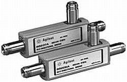
The 86200 series consists of two RF directional bridges differentiated by system impedance and frequency range. Both models share the same high-directivity, low-insertion-loss, flat-coupling-factor design approach — combining attributes that are typically found in either directional bridges or directional couplers but rarely in both. The choice between models is driven by the system impedance of the measurement environment and the upper frequency of the application.
Both bridges are specified for accurate reflection measurements and signal-leveling applications with scalar network analyzers, vector network analyzers, and spectrum analyzers. They share Type-N (female) connectors and the same chassis form factor. The technical difference between the two units is impedance and upper frequency limit, not measurement approach.
Each pre-owned model below is its own dedicated product page with condition-matched pricing and documentation. Select the page corresponding to the impedance and frequency coverage your measurement system requires.
The 86205A is the 50 Ω member of the family, covering 300 kHz to 6 GHz. This matches the standard impedance of general RF test and measurement instrumentation, including the 8753 family of RF vector network analyzers referenced in the datasheet.
The 86205A operates at 50 Ω impedance and extends to 6 GHz. The 86207A operates at 75 Ω impedance and extends to 3 GHz. Within their respective frequency ranges, the directivity profiles also differ: the 86205A specifies 40 dB directivity from 5 MHz to 2 GHz, while the 86207A specifies 40 dB directivity from 5 MHz to 1.3 GHz and 35 dB from 1.3 GHz to 2 GHz, with typical 30 dB from 2 GHz to 3 GHz.
Port match also varies between the two models. The 86205A is specified at 23 dB (1.15 SWR) from 0.3 MHz to 2.0 GHz and 20 dB (1.22 SWR) from 2.0 GHz to 3 GHz. The 86207A is specified at 20 dB (1.22 SWR) from 0.3 GHz to 1.3 GHz, with typical 18 dB (1.29 SWR) from 1.3 GHz to 3 GHz. Refer to the comparison table that follows for the detailed specification-by-specification breakdown across both models.
| Model | Frequency Range | Impedance | Max Directivity |
|---|---|---|---|
| 86207A | 300 kHz to 3 GHz | 75 Ω (nominal) | 40 dB (5 MHz to 1.3 GHz) |
| 86205A | 300 kHz to 6 GHz | 50 Ω (nominal) | 40 dB (5 MHz to 2 GHz) |
Additional differences in specifications beyond the few shown above are not listed here — see each model's full specifications below.
| Specification | Value |
|---|---|
| Frequency range | 300 kHz to 3 GHz |
| Impedance | 75 Ohms (nominal) |
| Directivity (25 °C, ±5 °C) | 30 dB, 0.3 MHz to 5 MHz 40 dB, 5 MHz to 1.3 GHz 35 dB, 1.3 GHz to 2 GHz (typical) 30 dB, 2 GHz to 3 GHz |
| Port match | 20 dB, 0.3 GHz to 1.3 GHz (1.22 SWR) (typical) 18 dB, 1.3 GHz to 2 GHz (1.29 SWR) (typical) 18 dB, 2 GHz to 3 GHz (1.29 SWR) |
| Operating temperature range | 0 °C to 55 °C |
Please review the Manufacturer's Data Sheet to verify published specifications. Feedback on this webpage is always welcome — please reach out to your Test Architect at any time for questions or concerns. Thank you, we truly appreciate you being our customer.
Model No
Agilent
Condition
Used
Manufacturer
Agilent

30+ Years in Business
Secure Payments
Sell Test Equipments
Knowledgeable Staff
On-site Lab
30+ Years in Business
Secure Payments
Sell Test Equipments
Knowledgeable Staff
On-site Lab
Request A Quote
 Chat Live
 Contact Us
 sales@valuetronics.com