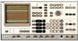
The HP 3585A is a spectrum analyzer covering 20 Hz to 40.1 MHz, designed for low-frequency through HF spectrum analysis where high resolution, wide dynamic range, and precision marker readout are required. The instrument combines a swept-tuned analyzer architecture with a built-in frequency counter, dual trace memories, and a tracking generator, providing a self-contained measurement platform for audio, low-frequency RF, communications, and component characterization work.
Spectrum analyzers in this frequency range and resolution class serve a specific role on the engineering bench: identifying signal energy versus frequency, measuring distortion and intermodulation products, characterizing filters and amplifiers with the tracking generator, and quantifying noise floors and spurious content. The 3585A's coverage from audio frequencies up through 40 MHz places it in the workflow of engineers working on audio systems, IF strips, low-frequency communications equipment, and precision component test where resolution bandwidths down to 3 Hz are needed to separate closely spaced signals.
ValueTronics International, LLC has been supplying test and measurement equipment since 1992 from our 20,000 square foot secure warehouse at 1675 Cambridge Drive in Elgin, Illinois. Every used instrument that ships from our facility is inspected, performance-checked against the manufacturer's published specifications, and graded by our technicians before it is listed. This is the difference between a description and a measurement — and on a precision instrument like a spectrum analyzer where small signals near large carriers are the application, the difference matters.
The 3585A was originally manufactured by Hewlett-Packard. HP's test and measurement business was spun off as Agilent Technologies in 1999, and the electronic measurement portion of Agilent was subsequently established as Keysight Technologies in 2014. Instruments bearing the HP, Agilent, or Keysight name on the front panel trace through the same engineering and product lineage.
| Specifications | |
|---|---|
| Frequency | |
| Measurement Range | 20 Hz to 40.1 MHz |
| Frequency Span | 0 Hz to 40.1 MHz settable with 0.1 Hz resolution; 10 Hz to 40 MHz in 1, 2, 5 steps |
| Frequency Span Accuracy | -0% +0.2% of Frequency Span setting |
| Marker Readout Accuracy | ±0.2% of Frequency Span ± Resolution Bandwidth |
| Counter Accuracy | ±0.3 Hz ± 1 x 10⁻⁷/month of counted frequency for a signal 20 dB greater than other signals and noise in the IF filter skirts |
| Manual Frequency Accuracy | ±0.1 Hz ± 1 x 10⁻⁷/month using the internal reference |
| Resolution Bandwidths | 3 dB bandwidths of 3 Hz to 30 kHz in a 1, 3, 10 sequence |
| Resolution Accuracy | ±20% at the 3 dB points |
| Selectivity (Shape Factor) | 60 dB/3 dB < 11:1 |
| Amplitude | |
| Measurement Range, Terminated (50/75 Ω) Input | -137 dBm to +30 dBm or equivalent level in dBV or volts |
| Measurement Range, High Impedance (1 MΩ) Input | 31 nV to 22 V |
| Vertical Scale | 10 division CRT settable to 10, 5, 2 and 1 dB/division relative to the Reference Level (which is represented by the top graticule line) |
| Input Range | -25 dBm to +30 dBm in 5 dB steps |
| Reference Level Settability | -100 dB to +10 dB; 0.1 dB resolution |
| Reference Level Accuracy, Terminated (50/75 Ω) Input | +10 dB to -50 dB: ±0.4 dB; -50 dB to -70 dB: ±0.7 dB; -70 dB to -90 dB: ±1.5 dB |
| Reference Level Accuracy, High Impedance (1 MΩ) Input (add to above) | 20 Hz to 10 MHz: ±0.7 dB; 10 MHz to 40.1 MHz: ±1.5 dB |
| Amplitude Linearity (referred to Reference Level) | 0 dB to -20 dB: ±0.3 dB; -20 dB to -50 dB: ±0.6 dB; -50 dB to -80 dB: ±1.0 dB; -80 dB to -95 dB: ±2.0 dB |
| Frequency Response, Terminated (50/75 Ω) Input | ±0.5 dB (referred to center of span) |
| Frequency Response, High Impedance (1 MΩ) Input | 20 Hz to 10 MHz: ±0.7 dB; 10 MHz to 40.1 MHz: ±1.5 dB |
| Input | |
| Signal Input, Terminated (50/75 Ω) | >26 dB return loss, DC coupled, BNC connector. Applied DC voltage must be ≤ ten times the RANGE setting in volts for full specification compliance |
| Signal Input, High Impedance (1 MΩ) | ±3% shunted by < 30 pF, BNC connector |
| Maximum Input Level, Terminated (50/75 Ω) | 13 V peak AC plus DC, relay protected against overloads to 42 V peak |
| Maximum Input Level, High Impedance (1 MΩ) | 42 V peak AC plus DC (derate AC by a factor of two for each octave above 5 MHz) |
| External Reference Input | 10 MHz (or subharmonic to 1 MHz), 0 dBm to +15 dBm/50 Ω. Required frequency accuracy ±5 x 10⁻⁶ |
| Dynamic Range | |
| Spurious Responses, Terminated (50/75 Ω) Input | < -80 dB |
| Spurious Responses, High Impedance (1 MΩ) Input | < -80 dB; except second harmonic distortion, < -70 dB |
| Intermodulation Distortion, Terminated (50/75 Ω) Input | < -80 dB; except 2nd order IM with one or both of the input signals within the range of 10 MHz to 40 MHz, < -70 dB |
| Intermodulation Distortion, High Impedance (1 MΩ) Input | < -70 dB |
| Residual Responses (no signal at input, -25 dBm Range) | < -120 dBm |
| LO Feedthrough | < -15 dB with respect to Range |
| Average Noise Level at 40 Hz (3 Hz Res. BW) | -123 dBm (1 Hz) using the Noise Level Key |
| Display | |
| Trace | Two memories, A and B, each 1001 data points horizontally by 1024 data points vertically displayed on the CRT at a flicker-free rate |
| Memory A | Updated at the rate of the analyzer sweep time |
| Memory B | Updated by transfer from A (Store A→B) |
| Max Hold | Retains in Memory A the largest signal level at each horizontal point over successive sweeps |
| A-B | Updates Memory A with sweep data minus Memory B data at each corresponding horizontal point |
| Trace Detection | Linear envelope detector used to obtain video information from the IF signal; peak signal excursions between horizontal sweep data points are retained and displayed at the left-hand data point |
| Output | |
| Tracking Generator Level | 0 dBm to -11 dBm/50 Ω with a single turn knob, continuously variable |
| Tracking Generator Frequency Accuracy | ±1 Hz relative to analyzer tuning |
| Tracking Generator Frequency Response | ±0.7 dB |
| Tracking Generator Impedance | 50 Ω; > 14 dB return loss |
| Probe Power | +15 Vdc, -12.6 Vdc; 150 mA max. Suitable for powering HP 1120A Active Probe |
| External Display X, Y | 1 volt full deflection |
| External Display Z | < 0 V to > 2.4 V |
| Recorder X Axis | Minimum of +10 Vdc full scale |
| Recorder Y Axis | +10 Vdc full scale |
| Recorder Z | Penlift output (TTL levels) |
| IF | 350 kHz, -14.0 dBV ± 2.0 dBV at the reference level |
| Video | +10 Vdc at the reference level |
| Frequency Reference | 10.000 MHz ± 1 x 10⁻⁷/mo., > +5 dBm into 50 Ω |
| Sweep | |
| Modes | Continuous, Single or Manual |
| Trigger | Free Run, Line, or External |
| Sweep Time Resolution | 0.2 sec |
| Sweep Time Minimum | 0.2 sec |
| Sweep Time Maximum | Frequency Span/minimum sweep rate limit. ≥ 10 kHz Res BW: 10 sec/Hz of Frequency Span or 0.1 Hz/sec. ≤ 3 kHz Res BW: 200 sec/Hz of Frequency Span or 0.005 Hz/sec |
| General | |
| Operating Temperature | 0°C to 55°C |
| Humidity | 95% RH except 300 Hz Res. BW, 40% RH |
| Warm-up Time | 20 minutes at ambient temperature |
| Power Requirements | 115 V (+11% -25%), 48-440 Hz; 230 V (+11% -18%), 48-66 Hz; < 180 watts, 3 A max. |
| Weight | 39.9 kg (88 lb) |
| Dimensions | 22.9 cm (9 in) H x 42.6 cm (16.75 in) W x 63.5 cm (25 in) D |
| Remote Operation | Compatible with IEEE Standard 488-1975 "Standard Digital Interface for Programmable Instrumentation" |
Please review the Manufacturer's Data Sheet to verify published specifications. Feedback on this webpage is always welcome — please reach out to your Test Architect at any time for questions or concerns. Thank you, we truly appreciate you being our customer.
Model No
HP
Condition
Used
Manufacturer
Agilent
Frequency
40 MHz

30+ Years in Business
Secure Payments
Sell Test Equipments
Knowledgeable Staff
On-site Lab
30+ Years in Business
Secure Payments
Sell Test Equipments
Knowledgeable Staff
On-site Lab
Request A Quote
 Chat Live
 Contact Us
 sales@valuetronics.com