The AWG5000 Series is a family of arbitrary waveform generators built to address the signal stimulus challenges faced by designers who need to verify, characterize, and debug sophisticated electronic designs. Each model pairs a 14-bit digital-to-analog converter with sample rates reaching 1.2 GS/s, two to four output channels, four to eight synchronized digital marker outputs, and up to 28 channels of digital data output. The instruments are built on an open Windows 7 platform, making them convenient to operate and straightforward to connect with peripherals and third-party software.
The series is applied across high-resolution wireless communications and defense electronics, education and research, ADC/DAC testing, and mixed-signal design and test. It is also used for real-world, ideal, or distorted signal generation — reproducing the glitches, anomalies, and impairments a design encounters in service — and for system synchronization and timing control across large-scale test systems. More broadly, the instruments address measurement challenges in wireless communications, defense electronics, digital consumer product design, data conversion equipment, test system synchronization, and semiconductor design and test.
ValueTronics stocks the AWG5000 Series from our own 20,000-square-foot secure warehouse at 1675 Cambridge Drive in Elgin, Illinois. Every pre-owned unit is inspected and functionally verified in-house by our technicians before it ships, while new units leave the factory sealed exactly as received.
The AWG5000 Series comprises three arbitrary waveform generator mainframes — the AWG5014C, AWG5012C, and AWG5002C — that share a common 14-bit DAC architecture, Windows 7 platform, and waveform-sequencing engine while differing in sample rate and output channel count. All three provide 14-bit resolution and 16M-point waveform memory per channel as standard, so the choice between models comes down to the channel count and sample-rate headroom an application requires.
Across the series the instruments share the same auxiliary outputs, automation interfaces, and software ecosystem, including the optional RFXpress signal-creation package. This shared foundation means a workflow developed on one model transfers directly to another, with the model differences confined to the front-end performance figures captured in the comparison table below.
Each pre-owned model below is listed on its own dedicated product page with condition-matched pricing. Select the model that fits your channel-count and sample-rate requirement, then choose the pre-owned unit that matches your budget and availability needs.
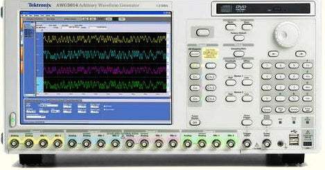
The AWG5014C is the only stand-alone arbitrary waveform generator in the series with four channels, which simplifies test setup and reduces measurement uncertainty. It pairs the series' top 1.2 GS/s sample rate with a total of eight marker outputs (two per channel) for system synchronization across large-scale test setups.
The models diverge primarily in two dimensions. The AWG5014C and AWG5012C both run at sample rates up to 1.2 GS/s, while the AWG5002C tops out at 600 MS/s. Channel count separates them further: the AWG5014C provides four output channels, whereas the AWG5012C and AWG5002C each provide two.
These differences cascade into the frequency-domain figures — effective frequency output, modulation bandwidth, and marker count all track the sample-rate and channel tier, with the AWG5014C carrying eight marker outputs against four on the two-channel models. Consult the comparison table that follows for the exact per-model sample rate, channel count, and bandwidth values.
| Model | Sample Rate | Channels | Max Output Frequency |
|---|---|---|---|
| AWG5014C | 1.2 GS/s | 4 | 480 MHz |
| AWG5012C | 1.2 GS/s | 2 | 480 MHz |
| AWG5002C | 600 MS/s | 2 | 240 MHz |
Additional differences in specifications beyond the few shown above are not listed here — see each model's full specifications below.
| Specification | Value |
|---|---|
| Digital to Analog Converter | |
| Sample rate | 10 MS/s to 1.2 GS/s |
| Resolution | 14 bit |
| Sin (x)/x roll-off (-1 dB) | 300 MHz |
| Sin (x)/x roll-off (-3 dB) | 520 MHz |
| Frequency Domain Characteristics | |
| Fmaximum (specified) | 480 MHz |
| Fmaximum (typical) | 540 MHz |
| Effective frequency switching time, Ts | 2.1 ns |
| Ts (typical) | 1.8 ns |
| Modulation bandwidth, -1 dB BW (typical) | Normal: Up to 130 MHz; Direct: Up to 180 MHz |
| Modulation bandwidth, -3 dB BW (typical) | Normal: Up to 230 MHz; Direct: Up to 300 MHz |
| Output amplitude range (typical) | Normal: -30 dBm to 17 dBm; Direct: -30 dBm to 0 dBm |
| Output amplitude resolution (typical) | 0.01 dB |
| Output amplitude accuracy (typical) | At 0 dBm level, with no offset, ±0.3 dB |
| Output flatness (typical) | ±1.0 dB, from 10 MHz to 480 MHz |
| Digital Data Out (Option 3) | |
| Number of outputs | 14-bit output on Ch1 and Ch2 (28 total) |
| Output connector | SMB (rear panel), single ended |
| Output impedance | 50 Ω |
| Levels - Window (into 50 Ω) | -1.0 V to 2.7 V |
| Levels - Amplitude | 0.1 Vp-p to 3.7 Vp-p |
| Levels - Resolution | 10 mV |
| Levels - Accuracy | ±(10% of setting + 120 mV) |
| Current (max) | ±54 mA per channel |
| Rise/fall time (20% to 80%) | 300 ps (1.0 Vp-p, Hi: 1.0 V, Lo: 0 V) |
| Delay from marker | -41 ns to -82 ns |
| Skew between outputs | <400 ps |
| Time Domain Characteristics | |
| Bit rate (typical) | 300 Mb/s |
| Rise/fall time, Tr/Tf (10% to 90%) | Normal: 1.4 ns; Direct: 0.95 ns |
| Rise time bandwidth (-1 dB) (typical) | Normal: 140 MHz; Direct: 210 MHz |
| Rise time bandwidth (-3 dB) (typical) | Normal: 250 MHz; Direct: 370 MHz |
| Low-pass filter | Normal: Bessel type, 50 and 100 MHz |
| Output amplitude range | Normal: 40 mVp-p to 9.0 Vp-p; Direct: 40 mVp-p to 1.2 Vp-p |
| Output amplitude resolution | 1.0 mV |
| Output amplitude accuracy | At 0.5 V, with no offset, ±(2% of amplitude + 2 mV) |
| Offset range | Normal: ±2.25 V |
| Offset resolution | 1.0 mV |
| Offset accuracy | At minimum amplitude, ±(2.0% of offset + 15 mV) |
| Output Distortion Characteristics | |
| SFDR (direct, typical) DC to 10 MHz carrier | -70 dBc |
| SFDR 10 to 20 MHz carrier | -70 dBc |
| SFDR 20 to 40 MHz carrier | -62 dBc |
| SFDR 40 to 80 MHz carrier | -62 dBc |
| SFDR 80 to 150 MHz carrier | -58 dBc |
| SFDR 150 to 300 MHz carrier | -58 dBc |
| SFDR 300 to 480 MHz carrier | -56 dBc |
| Harmonic distortion (37.5 MHz output) | Normal: <40 dBc; Direct: <49 dBc |
| Non-harmonic distortion (spurious) | < -60 dBc |
| Phase noise (typical) | < -85 dBc/Hz at 10 kHz offset |
| Random jitter (typical) | Normal: 5.0 ps |
| Total jitter (typical) | Normal: 150 ps at 0.5 Gb/s |
| Hardware Characteristics | |
| Number of outputs | 4 channels |
| Output connector | Differential, BNC (front panel) |
| Output impedance | 50 Ω |
| Waveform length | Standard: to 16M points; Extended memory: to 32M points |
| Number of waveforms | 1 to 16,200 |
| Sequence length/counter | 1 to 8,000 steps; 1 to 65,536 count |
| Run modes | Continuous, Triggered, Gated, Sequence, Jump |
| Sampling Clock | |
| Resolution | 8 digits |
| Accuracy | Within ±(1 ppm + Aging); Aging: within ±1 ppm per year |
| Internal Trigger Generator | |
| Range | 1.0 µs to 10.0 s |
| Resolution | 3 digits, 0.1 µs minimum |
| Output Skew Control | |
| Range | -5 ns to 5 ns |
| Resolution | 5 ps |
| Auxiliary Output Characteristics | |
| Markers - Number | Total of 8 (2 per channel) |
| Markers - Style | Single-ended |
| Markers - Connector | BNC (front panel) |
| Markers - Impedance | 50 Ω |
| Markers - Level Window | -2.0 V to 5.4 V |
Important: Not updated to comply with the RoHS 2 Directive 2011/65/EU; will not be shipped to the EU.
Important: Option 03 (28-channel digital data outputs) and Option 0309 (Opt. 03 + Opt. 09) must be ordered at time of purchase.
Important: Channel count listed conservatively as 2 for the AWG5012C: the datasheet's Hardware Characteristics table groups the AWG5012C with the AWG5014C as '4 channels,' but the Ordering Information section and the marker count (Total of 4, 2 per channel) identify the AWG5012C as a 2-channel instrument; verify the channel count for the specific unit.
Recommended pairing: the SMA cable (012-1690-xx) and SMB cable (012-1503-xx) listed among the series' recommended accessories.
This pre-owned unit is inspected and functionally verified in-house before it ships and is backed by our pre-owned warranty. To confirm its exact condition, firmware revision, installed options, or included accessories for your application before ordering, contact our Test Architects.
ValueTronics supplies both new and used test and measurement equipment. New units ship factory-sealed, exactly as received from the manufacturer; every used unit is inspected and functionally verified in-house at our 20,000 sq ft secure facility in Elgin, Illinois before it ships. Our Test Architects can help you select the condition, calibration, and configuration that fit your application.
Please review the Manufacturer's Data Sheet to verify published specifications. Feedback on this webpage is always welcome — please reach out to your Test Architect at any time for questions or concerns. Thank you, we truly appreciate you being our customer.
Model No
Tektronix
Condition
Pre-Owned
Manufacturer
Tektronix
Arb_gen_freq
480 MHz

30+ Years in Business
Secure Payments
Sell Test Equipments
Knowledgeable Staff
On-site Lab
30+ Years in Business
Secure Payments
Sell Test Equipments
Knowledgeable Staff
On-site Lab
Request A Quote
 Chat Live
 Contact Us
 sales@valuetronics.com