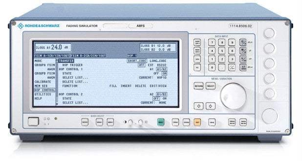

The characteristics of a radio channel can strongly impair signal transmission between a transmitter and in particular a moving receiver. The Baseband Fading Simulator R&S®ABFS generates signals that simulate real receive conditions in mobile applications. Thus, the response of receivers under real-world conditions can already be checked during development and QM acceptance testing. The simulation of fading signals at baseband level reduces costs.
Advantages of baseband fading simulation
Conventional fading simulators normally convert the signal of the radio channel to the IF, perform fading and then reconvert the signal to its RF frequency. It is, however, less costly to loop in the simulator prior to the first conversion to the carrier frequency, i.e. to simulate at baseband level (I and Q) and then convert to the correct frequency in the test system (see Fig. 3). Signals will therefore not be impaired by the effects of multiple conversion. This baseband fading simulation makes upgrading to new networks or standards easy.
The flexible concept of the R&S®ABFS allows the simulation of radio channels of existing and future communications systems (e.g. mobile radio, broadcasting, flight telephone, WLL, or WLAN systems).
The R&S®ABFS can also simulate frequency hopping systems. The R&S®ABFS is fast enough to follow the frequency hopping of a test system, for example within a frame of 4.616 ms (GSM frame time).
Furthermore, an offset voltage for each I and Q input or output can be entered to compensate for external DC offset voltages.
Together with a baseband source (e.g. the I/Q Modulation Generator R&S®AMIQ, see Fig. 1), receiver tests can be performed at the I/Q level even if the corresponding RF link is not available. During the development of receivers or correction circuits in the receiver (e.g. equalizer), the effects of fading can thus be checked at a very early stage.
Fit for the future
Baseband Fading Simulator ABFS is suitable for universal mobile radio applications in research, development and production. It comprises all scenarios and statistical models for simulating sporadic fading as specified in the test regulations of mobile radio standards (eg GSM, IS-54/US-136 or IS-95 CDMA).
The flexible concept of ABFS allows the simulation of radio channels of existing and future communication systems (eg mobile radio, broadcasting, flight telephone, WLL, or WLAN systems).
ABFS can also simulate frequency hopping systems. ABFS is fast enough to follow the frequency hopping of a test system for example within a frame of 4,616 ms (GSM frame time).
Furthermore, an offset voltage for each I and Q input or output can be entered to compensate external DC offset voltages.
Together with a baseband source (eg I/Q Modulation Generator AMIQ from Rohde & Schwarz, see Fig. 1 on the left) receiver tests can be performed at I/Q level even if the corresponding RF link is not available. During the development of receivers or correction circuits in the receiver (eg equalizer), the effects of fading can thus be checked at a very early stage.
The basic model of ABFS comes with two independent channels for 6-path fading. The two channels can be interconnected as follows:
Model No
ABFS
Condition
Used
Manufacturer
Rohde & Schwarz
B2
Second Fading Simulator
Hey👋Let's start with your email