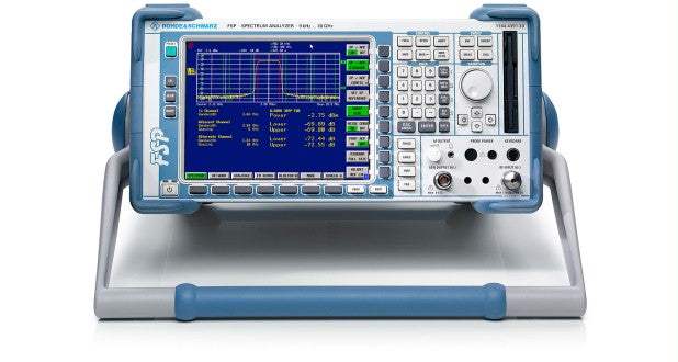
The Rohde & Schwarz FSP38 is a benchtop spectrum analyzer covering a continuous frequency range of 9 kHz to 40 GHz. It presents signal amplitude against frequency on an 8.4-inch TFT color display and combines a wide measurement span with fine frequency resolution down to 0.01 Hz, internal frequency-counter readout, and a comprehensive set of resolution and video bandwidth filters.
A spectrum analyzer measures how a signal's power is distributed across frequency, letting an engineer see carriers, harmonics, spurious products, and noise that a time-domain instrument cannot resolve. The FSP38 supports this work with selectable resolution bandwidths from 10 Hz to 10 MHz in 1-/3- steps, dedicated EMI bandwidths of 200 Hz, 9 kHz, and 120 kHz, FFT filters from 1 Hz to 30 kHz, and a full complement of trace detectors including Max Peak, Min Peak, Auto Peak, Sample, Quasi-Peak, Average, and RMS.
ValueTronics stocks and ships this equipment from its own 20,000-square-foot secure warehouse at 1675 Cambridge Drive in Elgin, Illinois. Every pre-owned instrument is inspected and functionally verified in-house before it ships, while new units leave factory-sealed exactly as received from the manufacturer.
Rohde & Schwarz was founded in 1933 in Munich, Germany, by Lothar Rohde and Hermann Schwarz. It has remained an independent, privately held company operating under the same name throughout its history, with no major acquisitions or rebrands altering the brand identity.
| Specification | Value |
|---|---|
| Frequency | |
| Frequency range | 9 kHz to 40 GHz |
| Frequency resolution | 0.01 Hz |
| Reference frequency, internal nominal — Aging per year (after 30 days of operation) | 1 × 10^-7 |
| Reference frequency, internal nominal — Temperature drift (0 to 50°C) | 1 × 10^-8 |
| External reference frequency | 10 MHz |
| Frequency display | with marker or frequency counter |
| Marker resolution | span / 500 |
| Max deviation (sweep time > 3⋅x auto sweep time) | ± ( frequency x reference accuracy + 0.5% x span + 10% x RBW + 1/2 LSD ) |
| Frequency counter resolution | 0.1 Hz to 10 kHz (selectable) |
| Count accuracy (S/N >25 dB) | ± (frequency x reference error + 1/2 (last digit)) |
| Frequency span | 0 Hz, 10 Hz to 40 GHz |
| Max span deviation | 0.1% |
| Spectral purity — SSB phase noise, f ≤ 500 MHz (dBc/(1Hz)) | |
| Carrier offset 100 Hz | <-84, typ -90 |
| Carrier offset 1 kHz | <-100, typ. -108 |
| Carrier offset 10 kHz | <-106, typ. -113 |
| Carrier offset 100 kHz (span >100 kHz) | <-110, typ. -113 |
| Carrier offset 1 MHz (span >100 kHz) | <-120, typ. -125 |
| Carrier offset 10 MHz | typ. -145 |
| Residual FM (f ≤ 500 MHz, RBW 1kHz, SWT 100ms) | typ. 3 Hz |
| Sweep time | |
| Span ≥ 10 Hz | 2.5 ms to 16000 s |
| Span ≥ 10 Hz — Max deviation | 1 % |
| Span 0 Hz | 1 us to 16000 s |
| Span 0 Hz — resolution | 125 ns |
| Resolution bandwidths | |
| Bandwidths | 10 Hz to 10 MHz (-3 dB) in 1-, 3- steps |
| EMI-Bandwidths | 200 Hz, 9 kHz, 120 kHz (-6 dB) |
| Bandwidth accuracy ≤ 100 kHz | < 3 % |
| Bandwidth accuracy 300 kHz to 3 MHz | < 10 % |
| Bandwidth accuracy 10 MHz | +10 %, –30 % |
| Shape factor –60dB / -3 dB, ≤ 100 kHz | ≤ 5 :1 (gaussian filters) |
| Shape factor –60dB / -3 dB, 300 kHz to 3 MHz | < 15 :1 (4-pole synchronous tuned filters) |
| Shape factor –60dB / -3 dB, 10 MHz | < 7 : 1 |
| Shape factor –60dB / -6 dB, EMI bandwidths | ≤ 5 : 1 |
| Video bandwidths | 1 Hz to 10 MHz in 1-, 3-steps |
| FFT filter | |
| Bandwidths | 1 Hz to 30 kHz (- 3 dB) in 1-, 3-steps |
| Bandwidth accuracy | 5 %, nominal |
| Shape factor –60dB / -3 dB | 2.5 : 1 nominal |
| Level | |
| Display range | displayed average noise level to 30 dBm |
| Maximum input level — DC voltage | 0 V |
| RF attenuation 0 dB — CW RF power | 20 dBm |
| RF attenuation 0 dB — Pulse spectral density | 97 dBµV (1MHz) |
| RF attenuation ≥10 dB — CW RF power | 30 dBm |
| RF attenuation ≥10 dB — Max. pulse voltage | 50 V |
| RF attenuation ≥10 dB — Max. pulse energy (10 µs) | 0.5 mWs |
| 1-dB compression of input mixer (0-dB RF Attenuation, f>200 MHz) | 0 dBm nominal |
| Intermodulation | |
| 3rd-order intermodulation — Intermodulation free dynamic range, level | 2 x -30 dBm, ∆f > 5 ⋅ RBW or 10 kHz, whichever is larger |
| 3rd-order intermodulation, 20 to 200 MHz | >70 dBc, T.O.I. >5 dBm |
| 3rd-order intermodulation, 200 MHz to 3 GHz | >74 dBc, T.O.I. >7 dBm |
| 3rd-order intermodulation, 3 GHz to 40 GHz | >70 dBc, T.O.I. >5 dBm |
| Second harmonic Intercept point (S.H.I), < 100 MHz | 25 dBm |
| Second harmonic Intercept point (S.H.I), 100 MHz to 3 GHz | 35 dBm |
| Second harmonic Intercept point (S.H.I), 3 GHz to 40 GHz | 45 dBm |
| Displayed average noise level (0-dB RF attenuation, RBW 100 Hz, VBW 1 Hz, 20 averages, trace average, span 0 Hz, termination 50 Ohm) | |
| 9 kHz | Typ -90 dBm |
| 100 kHz | <-90 dBm |
| 1 MHz | <-100, typ. -125 dBm |
| 10 MHz to 7 GHz | <-120, typ. -143 dBm |
| 7 GHz to 13 GHz | <-115, typ. -138 dBm |
| 13 to 26.5 GHz | <-100, typ. –110 dBm |
| 26.5 to 40 GHz | <-95, typ. –100 dBm |
| Immunity to interference | |
| Image frequency | > 70 dB |
| Intermediate frequency (f < 3 GHz) | > 70 dB |
| Spurious response (f >200 kHz, without input signal, 0-dB attenuation) | < -100 dBm |
| Spurious response (with input signal, f < 7 GHz, mixer level <–10 dBm, ∆f > 100 kHz) | < -70 dBc |
| Level display | |
| Screen | 501 × 400 pixel (one diagram), max. 2 diagrams with independent settings |
| Log level axis | 10 dB to 200 dB, in steps of 10 dB |
| Linear level axis | 10% of reference level per level division, 10 divisions or logarithmic scaling |
| Trace | max. 3, with two diagrams on screen max 3 per diagram |
| Trace Detector | Max. Peak, Min. Peak, Auto Peak, Sample, Quasi-Peak, Average, RMS |
| Trace Functions | Clear/Write, Max. Hold, Min. Hold, Average |
| Setting range of reference level — Logarithmic level display | –130 to 30 dBm, in steps of 0.1 dB |
| Setting range of reference level — Linear level display | 70.71 nV to 7.07 V in steps of 1% |
| Units of level axis | dBm, dBmV, dBµV, dBµA, dBpW (log level display); mV, µV, mA, µA, pW, nW (linear level display) |
| Max uncertainty of Level measurement | |
| Absolute level at 128 MHz, -30dBm (RF attenuation 10 dB, RBW 10 kHz, Ref. level –20 dBm, room temperature) | < 0.2 dB |
| Frequency response, 9 kHz to 3 GHz | < 0.5 dB |
| Frequency response, 3 to 26.5 GHz | < 2 dB |
| Attenuator | < 0.2 dB |
| Reference level setting | < 0.2 dB |
| Display nonlinearity Log/Lin (S/N >16 dB), RBW ≤ 100 kHz, 0 to –70 dB | < 0.2 dB |
| Display nonlinearity Log/Lin (S/N >16 dB), RBW ≤ 100 kHz, –70 to –90 dB | < 0.5 dB |
| Display nonlinearity Log/Lin (S/N >16 dB), RBW ≥ 300 kHz, 0 to –50 dB | < 0.2 dB |
| Display nonlinearity Log/Lin (S/N >16 dB), RBW ≥ 300 kHz, –50 to –70 dB | < 0.5 dB |
| Bandwidth switching (ref.: RBW = 10 kHz), 10 Hz to 100 kHz | < 0.1 dB |
| Bandwidth switching (ref.: RBW = 10 kHz), 300 kHz to 10 MHz | < 0.2 dB |
| Trigger functions | |
| Trigger, Span ≥ 10 Hz — Trigger source | free run, video, external, IF-level |
| Trigger, Span ≥ 10 Hz — Trigger offset | 125 ns to 100 s, resolution 125 ns min. (or 1% of offset) |
| Span = 0 Hz — Trigger source | free run, video, external, IF-level |
| Span = 0 Hz — Trigger offset | ± 125 ns to 100 s, resolution 125 ns min., dependent on sweep time |
| Span = 0 Hz — Delay time accuracy | ± (125 ns + (0.1% x delay time)) |
| Gated sweep — Trigger source | external, IF-level, Video |
Important: Maximum input levels: 20 dBm CW RF power at 0 dB RF attenuation, 30 dBm CW RF power at RF attenuation >=10 dB, 50 V maximum pulse voltage, and 0 V DC voltage.
This pre-owned unit is inspected and functionally verified in-house before it ships and is backed by our pre-owned warranty. To confirm its exact condition, firmware revision, installed options, or included accessories for your application before ordering, contact our Test Architects.
ValueTronics supplies both new and used test and measurement equipment. New units ship factory-sealed, exactly as received from the manufacturer; every used unit is inspected and functionally verified in-house at our 20,000 sq ft secure facility in Elgin, Illinois before it ships. Our Test Architects can help you select the condition, calibration, and configuration that fit your application.
Please review the Manufacturer's Data Sheet to verify published specifications. Feedback on this webpage is always welcome — please reach out to your Test Architect at any time for questions or concerns. Thank you, we truly appreciate you being our customer.
Model No
Rohde
Condition
Pre-Owned
Manufacturer
Rohde & Schwarz
Spec_ana_freq
9 kHz to 40 GHz
FS-K9
Power Sensor Measurements
FSP-B10
External Generator Control for all FSP models
FSP-B16
LAN Interface
FSP-B4
OCXO Reference Frequency

30+ Years in Business
Secure Payments
Sell Test Equipments
Knowledgeable Staff
On-site Lab
30+ Years in Business
Secure Payments
Sell Test Equipments
Knowledgeable Staff
On-site Lab
Request A Quote
 Chat Live
 Contact Us
 sales@valuetronics.com