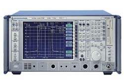
The R&S FSIQ is a signal analyzer that combines spectrum analysis, time-domain analysis, and modulation analysis in a single unit. It performs comprehensive measurement functions across the frequency, time, and modulation domains, with an integrated vector signal analyzer that handles both digitally and analog modulated signals. The series comprises three models distinguished by frequency coverage: the R&S FSIQ3 (20 Hz to 3.5 GHz), the R&S FSIQ7 (20 Hz to 7 GHz), and the R&S FSIQ26 (20 Hz to 26.5 GHz).
The R&S FSIQ is built for measurements on digital and analog mobile radio systems. In the frequency domain it measures intermodulation and harmonics and is suited to adjacent-channel power ratio (ACPR) measurements across mobile radio systems, with particular emphasis on WCDMA — it attains a WCDMA ACPR value of 75 dB in 4.096 MHz integration bandwidth, already reached at a −12 dBm input level. The instrument also supports burst analysis in TDMA systems such as GSM and NADC, power ramp (power-time template) measurements, transmitter transient measurement, and measurement of incidental phase modulation and AM-to-φM conversion.
ValueTronics stocks and holds its own test-and-measurement inventory in a 20,000 sq ft secure warehouse at 1675 Cambridge Drive in Elgin, Illinois. Every pre-owned unit is sourced and fulfilled directly from that facility; pre-owned units are inspected and functionally verified in-house by our technicians before they ship, while new units ship factory-sealed exactly as received from the manufacturer.
Rohde & Schwarz is a privately held company headquartered in Munich, Germany. It has operated continuously under the Rohde & Schwarz name with no major corporate rebrand or acquisition affecting the brand.
The R&S FSIQ is offered as three models that share the same one-box architecture for frequency-, time-, and modulation-domain analysis and differ primarily in upper frequency limit. The R&S FSIQ3 covers 20 Hz to 3.5 GHz, the R&S FSIQ7 covers 20 Hz to 7 GHz, and the R&S FSIQ26 covers 20 Hz to 26.5 GHz, with all three sharing the integrated vector signal analyzer, resolution bandwidths of 1 Hz to 10 MHz, and the 24 cm TFT colour display.
Because the three models share the same measurement functions, the selection between them is driven mainly by the frequency coverage an application requires, along with the model-specific performance values noted in the comparison table below.
Each model below links to its own dedicated product page with condition-matched pricing. Select the pre-owned listing for the specific frequency range your application requires, and review that page for its full per-model specifications.
The models differ in upper frequency limit (3.5 GHz, 7 GHz, and 26.5 GHz) and in several model-specific specifications. The minimum 5 ms full-span sweep time applies to the R&S FSIQ3 and R&S FSIQ7. The third-order intercept point is specified at +20 dBm (typ.) for the R&S FSIQ7 and +22 dBm (typ.) for the R&S FSIQ26, and total level uncertainty and frequency-response error limits widen at the higher frequency bands.
The R&S FSIQ26 uses an N/3.5 mm adapter connector system at its RF input and supports external and harmonic mixers (40 GHz to 110 GHz options) for measurements above its base range, and it ships with N-female and 3.5 mm-female test-port adapters. Power consumption and weight also rise across the series, from 195 VA / 24 kg for the R&S FSIQ3 to 245 VA / 26.5 kg for the R&S FSIQ26. Refer to the comparison table for the exact per-model values.
| Model | Frequency Range | 3rd-Order Intercept (TOI) | SSB Phase Noise (10 kHz offset, f ≤500 MHz) |
|---|---|---|---|
| FSIQ3 | 20 Hz to 3.5 GHz | TOI >12 dBm (18 dBm typ.) | < –120 dBc(1 Hz) |
| FSIQ7 | 20 Hz to 7 GHz | TOI >15 dBm (20 dBm typ.) | < –114 dBc(1 Hz) |
| FSIQ26 | 20 Hz to 26.5 GHz | TOI >17 dBm (22 dBm typ.) | < –114 dBc(1 Hz) |
Additional differences in specifications beyond the few shown above are not listed here — see each model's full specifications below.
| Specification | Value |
|---|---|
| Frequency | |
| Frequency range | 20 Hz to 3.5 GHz |
| Display range for frequency axis | 0 Hz, 10 Hz to 3.5 GHz |
| Spectral purity (dBc(1 Hz)) SSB phase noise, f ≤500 MHz | |
| Carrier offset 100 Hz | < –87 |
| Carrier offset 1 kHz | < –107 |
| Carrier offset 10 kHz | < –120 |
| Carrier offset 100 kHz | < –119 |
| Carrier offset 1 MHz | < –138 |
| Intermodulation | |
| 3rd-order Intercept (TOI), Δf >5 x RBW or 10 kHz | >64 dBc for f >100 MHz (TOI >12 dBm, 18 dBm typ.) |
| Second harmonic intercept point (SHI) | >25 dBm, >40 dBm typ. for f <50 MHz; >45 dBm, >50 dBm typ. for f >50 MHz |
| Displayed average noise level (DANL) (0 dB RF attenuation, RBW 10 Hz, VBW 1 Hz, 20 averages, trace average, span 0 Hz, termination 50 Ω) | |
| 20 Hz | <–80 dBm |
| 1 kHz | <–110 dBm |
| 10 kHz | <–125 dBm |
| 100 kHz | <–135 dBm |
| 1 MHz | <–145 dBm, –150 dBm typ. |
| 10 MHz to 6 GHz | <–145 dBm, –150 dBm typ. |
| Maximum dynamic range | |
| 1 dB compression to DANL (RBW 1 Hz) | 170 dB |
| Immunity to interference | |
| Image rejection | >80 dB, >90 dB typ. |
| Intermediate frequency | >100 dB |
| Other interfering signals (mixer level <10 dBm) | <–80 dB |
| Level (frequency response, 10 dB RF atten.) | |
| Absolute error limit at 120 MHz | <0.3 dB |
| <2.2 GHz | <0.5 dB |
| 2.2 GHz to 3.5 GHz | <1 dB |
| Total measurement error limit (20°C to 30°C, RBW 5 kHz to 1 MHz, signal 0 dB to 70 dB below ref. level) | |
| <2.2 GHz | <1 dB |
| 2.2 GHz to 3.5 GHz | <1.5 dB |
| Digital demodulation residual error (EVM and magnitude error, f <1 GHz) | |
| Symbol rate ≤30 kHz | 0.5% rms |
| 30 kHz to 300 kHz | 1% rms |
| 300 kHz to 1 MHz | 2% rms |
| 1 MHz to 4.2 MHz | 2% rms |
| 4.2 MHz to 6.4 MHz | 2.4% rms |
| Phase error (f <1 GHz) | |
| Symbol rate ≤30 kHz | 0.3° rms |
| 30 kHz to 300 kHz | 0.5° rms |
| 300 kHz to 1 MHz | 1.5° rms |
| 1 MHz to 4.2 MHz | 1.5° rms |
| 4.2 MHz to 6.4 MHz | 2° rms |
| Inputs and outputs (front panel) | |
| RF input | N female, 50 Ω |
| VSWR (RF attenuation ≥10 dB), f <3.5 GHz | <1.5 |
| General data | |
| Power consumption | 195 VA |
| Weight | 24 kg |
Important: Recommended calibration interval: 1 year (2 years for operation with an external reference).
Important: Options R&S FSE-B12 (Switchable Attenuator for Tracking Generator) and R&S FSE-B13 (1 dB Attenuator) cannot be installed simultaneously.
Important: The Removable Hard Disk R&S FSE-B18 cannot be retrofitted; it is factory-fitted only.
Important: The cdmaOne and WCDMA/3GPP application firmware (R&S FSIQ-K71/-K72/-K73) require the DSP and I/Q Memory Extension R&S FSIQ-B70; additional modifications may be required if the R&S FSIQ-B70 is retrofitted.
Important: EDGE Application Firmware Extensions R&S FSE-K20/-K21 require R&S FSE-K10/-K11 respectively.
Recommended pairing: add the optional Tracking Generator with I/Q Modulator — R&S FSE-B9 for the R&S FSIQ3, or R&S FSE-B11 for the R&S FSIQ7/26 — to generate AM signals with very low incidental FM/φM.
This pre-owned unit is inspected and functionally verified in-house before it ships and is backed by our pre-owned warranty. To confirm its exact condition, firmware revision, installed options, or included accessories for your application before ordering, contact our Test Architects.
ValueTronics supplies both new and used test and measurement equipment. New units ship factory-sealed, exactly as received from the manufacturer; every used unit is inspected and functionally verified in-house at our 20,000 sq ft secure facility in Elgin, Illinois before it ships. Our Test Architects can help you select the condition, calibration, and configuration that fit your application.
Please review the Manufacturer's Data Sheet to verify published specifications. Feedback on this webpage is always welcome — please reach out to your Test Architect at any time for questions or concerns. Thank you, we truly appreciate you being our customer.
Model No
Rohde
Condition
Pre-Owned
Manufacturer
Rohde & Schwarz
Spec_ana_freq
3.5 GHz
B11
Tracking Generator 7 GHz with I/Q Modulator for R&S FSIQ7/26
B13
1 dB Input Attenuator
B15
Ethernet Adapter
B16
Ethernet (RJ45 connector) also has two variants.
B17
2nd IEC/IEEE Bus Interface
B22
Increased Level Accuracy up to 2 GHz
B4
Low Phase Noise
B5
FFT Bandwidths 1 Hz to 1 KHz
B7
Vector Signal Analyzer
B70
DSP and IQ Memory Extension
K72
W-CDMA BTS Analyzer
K74
3GPP HSDPA Base Station Test

30+ Years in Business
Secure Payments
Sell Test Equipments
Knowledgeable Staff
On-site Lab
30+ Years in Business
Secure Payments
Sell Test Equipments
Knowledgeable Staff
On-site Lab
Request A Quote
 Chat Live
 Contact Us
 sales@valuetronics.com