
Accessories:
Applications:
Electrical insulating materials deteriorate with time leading to breakdowns and costly repair bills. Insulation resistance testers apply a regulated DC voltage across the insulation and measure current low through it applying Ohm’s law to calculate insulation resistance. The current lows because no insulation material is perfect.
IR tester uses include:
Insulation testing with high voltage DC affects insulation polarisation such that consecutive testing without complete discharge of the unit under test will yield different results. Care should be taken to always employ the same process and technique of connecting to and testing an insulator to be able to trend results. It is important to record temperature of the insulation as well as IR values.
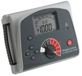
The Megger BM5200 tester is a battery powered instrument with digital and analogue arc display, designed for high voltage insulation resistance testing in the maintenance and servicing of cables, rotating plant machinery, transformers, switchgear and industrial installations.
DC insulation tests are performed at 250 V, 500 V, 1000 V, 2500 V and 5000 V. Insulation resistance measuring range is 100 kΩ to 1000 GΩ. Automatic discharge for capacitive circuits under test is provided and decaying voltage displayed.
The guard terminal can be used to minimise the effects of surface leakage and hence erroneous measurements when carrying out insulation resistance tests.
Three insulation resistance (IR) test modes are provided, (InS, PI and t) and available in any IR test range. In IR mode (InS) tests are initiated by pressing and holding down the TEST button for two seconds and terminated by a second press of the TEST button. A Polarisation Index (PI) mode performs a ratio metric test that calculates the ratio of insulation resistance at ten minutes to insulation resistance at one minute. The IR test timer (t) mode facilitates a single ixed time test based on the set time interval t.
For capacitive test objects the instrument will automatically discharge through an internal resistor and indicate voltage across the terminals in the range 25 V to 600 V with higher voltages indicated by ‘>600 V’. This feature will give decaying voltage indication following the testing of reactive loads. When the voltage indicator disappears it is safe for the user to disconnect the test leads.
The BM5200 is powered by eight 1.5 V IEC LR6 (AA) cells. Design safety features include high voltage warning indicator, external voltage display after IR test, automatic discharge of reactive loads and test leads.
Model No
BM5200
Condition
New
Manufacturer
Megger
Hey👋Let's start with your email