🎓 Request a Quote To Get An EDU Discount
Couldn't load pickup availability
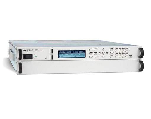
The Keysight E4360A Modular Solar Array Simulator is a dual-output programmable DC power source that simulates the output characteristics of a solar array. It is primarily a current source with very low output capacitance, capable of quickly reproducing the I-V curve of different arrays under different conditions such as temperature and age. A single 2U-high mainframe provides up to 2 outputs and up to 1200 W, and the platform is available either as an off-the-shelf instrument or integrated into a full turn-key solar array simulator system.
Solar array simulators are used in satellite test applications, where solar panels with unique I-V characteristics power the satellite and a specialized supply is needed to verify the satellite power system and the design of the power bus regulator on the ground. They are also used in residential photovoltaic test applications: a solar array simulator verifies that a microinverter tracks the maximum power point under varying environmental conditions such as sunny, cloudy, shadowing, and different temperatures, and confirms that the microinverter is reliable and efficient.
ValueTronics stocks and holds its own inventory in a 20,000 sq ft secure warehouse at 1675 Cambridge Drive in Elgin, Illinois. Every pre-owned unit is inspected and functionally verified in-house by our technicians before it ships, while new units ship factory-sealed exactly as received from the manufacturer.
The instrument's manufacturer traces its corporate lineage from Hewlett-Packard to Agilent Technologies, which was spun out in 1999, and then to Keysight Technologies in 2014. The brand has been evolving since 1939.
The E4360 is a modular platform built around the E4360A mainframe, which holds up to two solar array simulator modules in 2U of rack space and delivers up to 1200 W total. Buyers can order the mainframe and modules separately for self-assembly, or order a preconfigured, fully assembled mainframe shipped as a tested instrument.
Two simulator DC modules are offered: the E4361A and the E4362A, along with J-option variants of those modules. Preconfigured units pair an E4360A mainframe with two like modules, with the E4367A using two E4361A modules and the E4368A using two E4362A modules.
Each model linked below is its own dedicated product page with pre-owned condition-matched pricing. Select the configuration that matches your required output ratings and ordering options.
The modules differ in their output ratings as shown in the comparison table. The E4361A module is rated 65 V, 8.5 A, 510 W, while the E4362A module is rated 130 V, 5 A, 600 W; J-option variants such as the E4362A-J01 through -J05 and E4361A-J01 carry their own voltage, current, and power ratings. Across all modules the recommended calibration interval is 1 year and output terminal isolation is ±240 Vdc from chassis ground.
Preconfigured mainframes consolidate the choice: the E4367A is an E4360A mainframe with two E4361A modules and the E4368A is an E4360A mainframe with two E4362A modules, while the E4366A ships with two special-option modules. Refer to the comparison table for the per-model output power, voltage, and current ratings that distinguish each configuration.
| Model | Max Power | Max Voltage (Voc) | Max Current (Isc) |
|---|---|---|---|
| E4362A | 600 W | 130 V | 5 A |
| E4360A | 1200 W | — | — |
| E4361A | 510 W | 65 V | 8.5 A |
| E4367A | — | 65 V | 8.5 A |
Additional differences in specifications beyond the few shown above are not listed here — see each model's full specifications below.
| Specification | Value |
|---|---|
| Output Ratings (Simulator and Table Mode) | |
| Maximum power | 600 W |
| Maximum open circuit voltage (Voc) | 130 V |
| Maximum voltage point (Vmp) | 120 V |
| Maximum short circuit current (Isc) — line voltage 200/230/240 V | 5.0 A |
| Maximum current point (Imp) — line voltage 200/230/240 V | 5.0 A |
| Maximum short circuit current (Isc) — line voltage 100/120 V | 2.5 A |
| Maximum current point (Imp) — line voltage 100/120 V | 2.5 A |
| Output Ratings (Fixed Mode) | |
| Minimum impedance (∆V/∆Vl) | 1 Ω |
| Voltage | 0 - 120 V |
| Current — line voltage 200/230/240 V | 0 - 5.0 A |
| Current — line voltage 100/120 V | 0 - 2.5 A |
| Current derating factor (from 40 to 55 °C) | 0.069 A/°C |
| Output Voltage Ripple & Noise (20 Hz to 20 MHz) | |
| Simulator/table mode | 24 mVrms / 195 mVp-p |
| Fixed mode (constant voltage) | 30 mVrms / 150 mVp-p |
| Programming Accuracy (@ 23 ±5 °C) | |
| Fixed mode voltage | 0.075% + 50 mV |
| Fixed mode current | 0.2% + 10 mA |
| Readback Accuracy (@ 23 ±5 °C) | |
| Voltage | 0.08% + 50 mV |
| +Current | 0.20% + 10 mA |
| −Current | 0.35% + 24 mA |
| Load Regulation – Fixed Mode | |
| Constant voltage | 2 mV |
| Constant current | 1 mA |
| Line Regulation – Fixed Mode | |
| Constant voltage | 2 mV |
| Constant current | 1 mA |
| Output Current Ripple & Noise (20 Hz to 20 MHz) | |
| Simulator/table mode | 4 mArms / 32 mAp-p |
| Fixed mode (constant current) | 2.5 mArms / 19 mAp-p |
| Output Programming Range (maximum programmable values) | |
| Simulator/table mode voltage | 0 - 130 V |
| Fixed mode voltage | 0 - 123 V |
| Current — line voltage 200/230/240 V | 0 - 5.1 A |
| Current — line voltage 100/120 V | 0 - 2.55 A |
| Overvoltage protection | 0 - 140 V |
| Overcurrent limit | 0 - 6.25 A |
| Programming Resolution (average values) | |
| Voltage | 37 mV |
| Current | 1.6 mA |
| Overvoltage protection | 600 mV |
| Overcurrent limit | 27 mA |
| Programming Accuracy | |
| Overvoltage protection | 1.2 V |
| Overcurrent limit | 0.5% + 125 mA |
| Current monitor (referenced to P common) | 1.0% + 75 mA |
| Fixed Mode Analog Current Programming | |
| Analog programming | 1.0% + 3.2 mA |
| +Ip to −Ip differential input (0 to full scale) | 0 to -4 V |
| Max. common mode voltage (referenced to +OUT) | ±18 V |
| Nominal input impedance | 20 kΩ |
| Drift/Temperature Stability | |
| Voltage | 0.04% + 2 mV |
| Current | 0.1% + 0.5 mA |
| Temperature Coefficients (output change per °C) | |
| Voltage | 0.01% + 650 μV |
| Current | 0.025% + 125 μA |
| Other Supplemental Characteristics | |
| Output capacitance | < 50 nF |
| Maximum reverse diode current (with fans running) | 5.0 A |
| Output current settling time | < 5 μs |
| Maximum capacitive load (simulator/table & fixed mode) | 2000 μF |
| Load lead drop with remote sensing (simulator/table mode) | Up to 2 volts + (Voc - Vmp) |
| Load lead drop with remote sensing (fixed mode) | Up to 2 volts total |
| Current sinking capability (simulator/table mode) | 500 mA |
| Current sinking capability (fixed mode) | 440 mA |
| Voltage programming rise/fall time | < 8 ms |
| Voltage programming settling time | 25 ms typical |
| Auto-parallel configuration | Up to 4 outputs |
| Series and shunt switching frequency | 50 kHz maximum |
| Output terminal isolation (from chassis ground) | ±240 Vdc |
| Recommended calibration interval | 1 year |
Important: Maximum output power is limited to 600 W at 100/120 Vac; full 1200 W output requires Option 904 and operation at 220/240 Vac.
Important: When configuring a mainframe with fewer than 2 filled module slots, you MUST order a Filler Panel Kit (Option FLR or E4369A) to fill any empty module slot for proper operation; each kit contains one filler panel.
Important: For rack mounting, you MUST order the Rack Mount Kit (Option 908); standard rack mount hardware will not work.
Important: The mainframe has side air vents; 1U of space is required between the instruments to retain proper cooling.
Important: The unit may go out of specification when subjected to RF fields of 3 volts/meter in the frequency range of 26 MHz to 1 GHz.
Important: Electrostatic discharges greater than 1 kV near the I/O connectors may cause the unit to reset and require operator intervention.
Important: A power cord (line cord) option must be selected and ordered separately; it is not included by default with the mainframe.
This pre-owned unit is inspected and functionally verified in-house before it ships and is backed by our pre-owned warranty. To confirm its exact condition, firmware revision, installed options, or included accessories for your application before ordering, contact our Test Architects.
ValueTronics supplies both new and used test and measurement equipment. New units ship factory-sealed, exactly as received from the manufacturer; every used unit is inspected and functionally verified in-house at our 20,000 sq ft secure facility in Elgin, Illinois before it ships. Our Test Architects can help you select the condition, calibration, and configuration that fit your application.
Please review the Manufacturer's Data Sheet to verify published specifications. Feedback on this webpage is always welcome — please reach out to your Test Architect at any time for questions or concerns. Thank you, we truly appreciate you being our customer.
Model No
Keysight
Condition
Pre-Owned
Manufacturer
Keysight
Dcsup_amps
5 A
Dcsup_volts
130 V
Dcsup_watts
600 W

30+ Years in Business
Secure Payments
Sell Test Equipments
Knowledgeable Staff
On-site Lab
30+ Years in Business
Secure Payments
Sell Test Equipments
Knowledgeable Staff
On-site Lab
Request A Quote
 Chat Live
 Contact Us
 sales@valuetronics.com


