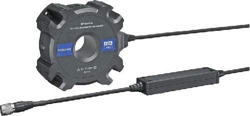
The CT6904 is an ultra-high-performance AC/DC current sensor from HIOKI built for the measurement of large currents up to 500 A (rms). It applies the zero-flux (fluxgate detection) measurement method, in which high-frequency current is detected with windings (CT method) and direct-to-low-frequency current is detected with fluxgates. A newly developed opposed split coil technology is used in the winding areas, achieving a wide measurement range from DC to 4 MHz — a range described as 40× that of conventional models — while a uniquely shaped solid aluminum shield surrounds the coil to eliminate the influence of surrounding voltage on the measurement.
The sensor targets the power electronics, natural energy, and automotive industries, where high inverter efficiency and improved power-saving performance are in demand. Listed applications include high-precision and efficiency testing of SiC/GaN inverters — where its flat frequency characteristics allow accurate measurement of both fundamental-wave current and switching-frequency current during PWM output — and reactor and transformer loss analysis for power converters, where its noise resistance lets switching current that had been obscured by noise be measured accurately. In these roles it is used together with a power analyzer to measure inverter input/output power and efficiency.
ValueTronics stocks and holds its own inventory in a 20,000 sq ft secure warehouse at 1675 Cambridge Drive, Elgin, Illinois, so the current sensors and companion instruments you order are on hand rather than sourced on demand.
| Specification | Value |
|---|---|
| Input, Output & Measurement (Basic Specifications) | |
| Rated primary current | 500 A AC/DC |
| Diameter of measurable conductors | φ 32 mm (1.26 in) or less |
| Maximum input current | Within derating shown in the derating figure. However, up to ±1000 A peak is allowable if within 20 ms (design value). When measuring current in the vicinity of derating, use a cooling time that is 10x or more greater than current input time. |
| Output voltage | 4 mV/A |
| Maximum rated voltage to ground | 1000 V CAT III; Expected transient overvoltage: 8000 V |
| Linearity | ±10 ppm Typical (23°C (73°F)) |
| Offset voltage | ±10 ppm Typical (23°C (73°F), no input) |
| Accuracy guarantee conditions | Guaranteed accuracy period: 1 year; after adjustment by Hioki: 1 year. Temperature and humidity for guaranteed accuracy: 23°C ±5°C (73°F ±9°F), 80% RH or less. Warm-up time: 30 min. or more. Input waveform: sine wave. Connection: measuring instrument with an input resistance of 0.9 MΩ to 1.1 MΩ. Terminal-to-ground voltage: 0 V, no external magnetic field, conductor center position. |
| Accuracy Specifications (Amplitude / Phase) | |
| DC | Amplitude: ±0.025% rdg. ±0.007% f.s.; Phase: — |
| DC < f < 16 Hz | Amplitude: ±0.2% rdg. ±0.02% f.s.; Phase: ±0.1° |
| 16 Hz ≤ f < 45 Hz | Amplitude: ±0.1% rdg. ±0.02% f.s.; Phase: ±0.1° |
| 45 Hz ≤ f ≤ 65 Hz | Amplitude: ±0.02% rdg. ±0.007% f.s.; Phase: ±0.08° |
| 65 Hz < f ≤ 850 Hz | Amplitude: ±0.05% rdg. ±0.007% f.s.; Phase: ±0.12° |
| 850 Hz < f ≤ 1 kHz | Amplitude: ±0.1% rdg. ±0.01% f.s.; Phase: ±0.4° |
| 1 kHz < f ≤ 5 kHz | Amplitude: ±0.4% rdg. ±0.02% f.s.; Phase: ±0.4° |
| 5 kHz < f ≤ 10 kHz | Amplitude: ±0.4% rdg. ±0.02% f.s.; Phase: ±(0.08×f)° |
| 10 kHz < f ≤ 50 kHz | Amplitude: ±1% rdg. ±0.02% f.s.; Phase: ±(0.08×f)° |
| 50 kHz < f ≤ 100 kHz | Amplitude: ±1% rdg. ±0.05% f.s.; Phase: ±(0.08×f)° |
| 100 kHz < f ≤ 300 kHz | Amplitude: ±2% rdg. ±0.05% f.s.; Phase: ±(0.08×f)° |
| 300 kHz < f ≤ 1 MHz | Amplitude: ±5% rdg. ±0.05% f.s.; Phase: ±(0.08×f)° |
| Frequency range | 4 MHz (±3 dB Typical) |
| Effects of temperature | Within -10°C to 18°C (14°F to 64°F) or 28°C to 50°C (82°F to 122°F): Amplitude sensitivity ±0.005% rdg./°C; Offset voltage ±0.005% f.s./°C; Phase ±0.01°/°C |
| Common-mode voltage rejection ratio (CMRR) | 140 dB or greater (50 Hz/60 Hz), 120 dB or greater (100 kHz) (Effect on output voltage/common-mode voltage) |
| Effect of conductor position | ±0.01% rdg. or less (100 A input, 50 Hz/60 Hz), when using wire with 10 mm (0.39 in) outer diameter |
| Combined Accuracy (PW6001 accuracy + CT6904 accuracy, f.s. = PW6001 Range) | |
| DC | Current: ±0.045% rdg. ±0.037% f.s.; Power: ±0.045% rdg. ±0.057% f.s. |
| 45 Hz ≤ f ≤ 65 Hz | Current: ±0.04% rdg. ±0.027% f.s.; Power: ±0.04% rdg. ±0.037% f.s. |
| Combined accuracy notes | For 10 A Range and 20 A Range, apply ±0.12% f.s. (f.s. = PW6001 Range). For other bandwidths, add PW6001 accuracy + CT6904 accuracy (consider sensor rating when calculating f.s. error). With CT9555: sensor accuracy x 1.5 (when the output coaxial cable is no longer than 1.6 m (5.25 ft)); for a 10 m output cable (made to order), frequency range 1 MHz (±3 dB Typical). |
| General Specifications | |
| Operating environment | Indoors, Pollution Degree 2, altitude up to 2000 m (6562.20 ft) |
| Operating temperature and humidity range | -10°C to 50°C (14°F to 122°F), and 80% RH or less (no condensation) |
| Storage temperature and humidity range | -20°C to 60°C (-4°F to 140°F), and 80% RH or less (no condensation) |
| Dielectric withstand voltage | 7.4 kV AC (sensed current of 1 mA), 50 Hz/60 Hz: 1 min (Distance between feed-through window and cable output terminal) |
| Power supply | Power supplied from PW6001, PW3390, and CT9555 |
| Max. power consumption | 7 VA (500 A/55 Hz measurement, with a power supply of ±12 V) |
| Interface | Dedicated interface (ME15W) |
| Dimensions | Approx. 139 mm (5.47 in) W × 120 mm (4.72 in) H × 52 mm (2.05 in) D (excluding protrusions and cables) |
| Output cable length | Approx. 3 m (9.84 ft) (including relay box). For a 10 m (32.81 ft) output cable (made to order): approx. 10 m (32.81 ft) (including relay box). |
| Bracket hole diameter | φ 5.2 mm (0.20 in) (M5 screws, Recommended tightening torque: 1.5 N·m to 2.0 N·m) |
| Mass | Approx. 1.0 kg (35.3 oz). For a 10 m output cable (made to order): approx. 1.3 kg (45.9 oz). |
| Product warranty period | 3 years |
Important: Maximum rated voltage to ground: 1000 V CAT III (expected transient overvoltage 8000 V).
Important: Maximum input current is limited by the derating curve. Up to ±1000 A peak is allowable if within 20 ms (design value). When measuring current in the vicinity of derating, use a cooling time that is 10x or more greater than the current input time.
Important: The CT6904 is powered from and connects to a compatible Hioki host instrument (POWER ANALYZER PW6001, POWER ANALYZER PW3390, or SENSOR UNIT CT9555) via the dedicated ME15W interface; a compatible host instrument is required to operate the sensor and is not part of the sensor's standard delivery.
Important: A 10 m (32.81 ft) output cable is available as a made-to-order option; with it, add an amplitude accuracy of ±(0.015×f)% rdg. for 50 kHz < f ≤ 1 MHz and the frequency range becomes 2 MHz (±3 dB Typical).
Recommended pairing: use the CT6904 with the HIOKI POWER ANALYZER PW6001 (also connectable to the PW3390 and SENSOR UNIT CT9555) to enable the phase-compensated, combined-accuracy measurements named in the specifications.
This is a brand-new, factory-sealed unit, supplied exactly as it arrives from the manufacturer and backed by the full manufacturer warranty. For the exact configuration, available options, included accessories, or current lead time for your application, our Test Architects can confirm the details before you order.
ValueTronics supplies both new and used test and measurement equipment. New units ship factory-sealed, exactly as received from the manufacturer; every used unit is inspected and functionally verified in-house at our 20,000 sq ft secure facility in Elgin, Illinois before it ships. Our Test Architects can help you select the condition, calibration, and configuration that fit your application.
Please review the Manufacturer's Data Sheet to verify published specifications. Feedback on this webpage is always welcome — please reach out to your Test Architect at any time for questions or concerns. Thank you, we truly appreciate you being our customer.
Model No
Hioki
Condition
Factory New
Manufacturer
Hioki
Curr_prob_freq
4 MHz

30+ Years in Business
Secure Payments
Sell Test Equipments
Knowledgeable Staff
On-site Lab
30+ Years in Business
Secure Payments
Sell Test Equipments
Knowledgeable Staff
On-site Lab
Request A Quote
 Chat Live
 Contact Us
 sales@valuetronics.com