
The ranges are as follows:
Full rated output power:
Input
General
Mechanical
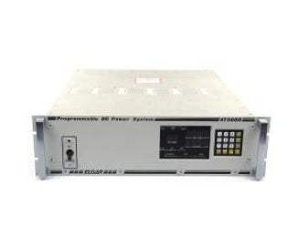
Elgar’s AT 8000A/B programmable multi output DC power system accepts both power supply and electronic load modules simultaneously in a single high density 5- 1/4" mainframe. Up to six fully independent channels of linear DC power and/or DC loads can be accommodated in one 19" wide rackmount chassis. The system can be expanded to 16 channels in master/ expansion chassis configurations. It can be controlled either locally from the front- panel keyboard or remotely via IEEE- 488 GPIB using one selectable bus address. With the built- in test option, readback capability is available for voltage and current readings on DC power modules, Auxiliary Drive Modules (ADM’s) and electronic DC loads.
High Density Mainframe
Six 200W DC power supply modules and/or 300W electronic loads can fit into one 5- 1/4" mainframe. By paralleling power modules, a single chassis can deliver up to 1200W. Up to 16 independent channels of DC power can be controlled on a single selectable GPIB address for up to 19.2 kW in a multi- chassis system.
Power and Electronic Load Modules in the same Chassis
AT 8000A/B can house both DC power and electronic load modules in the same chassis, operating simultaneously. DC power systems for ATE applications can be configure d in one package that would otherwise require a multiple chassis solution.
Front Panel Keyboard/Display
A 16- pad multi- level keyboard features increment/decrement keys plus LED’s and displays to speed and simplify programming. The system can show programmed values or, with the built- in test option, actual measured values of voltage and current as well as channel numbers, disconnect status, sense status and modes of operation.
Internal Programmer
A choice of either ABLE (Atlas Based Language Extension) or optional CIIL (Control Interface Intermediate Language) for MATE applications provides complete voltage, current and general system control via the IEEE- 488 GPIB.
Local/Manual Control
The AT 8000A/B allows local or manual control of most functions, alerts the operator to identified system malfunctions and provides prompting for ease of programming and operation.
Programming
Atlas Based Language Extension (ABLE) provides simple, easy to use mnemonics for concise programming. Control Interface Intermediate Language (CIIL) conforms to U.S. Air Force MATE guidelines.
AT8000B Series
For special ATE applications requiring European CE marking, we offer the AT 8000B Series. Designed as a modular DC voltage system, it is provided with GPIB programming and provides the same features of the standard AT 8000A series. Voltage modules up to 80 VDC are available.
Applications
Elgar’s modular AT 8000A system offers fully programmable DC power modules and DC loads. The principal applications for the AT 8000A are ATE in production test environments, incoming inspection, repair facilities and quality control where it can be used to provide power stimulus for subassemblies or PCB’s. Configured as a load system, the AT 8000A enables the end- user to perform the dynamic loading of DC power supplies, which insures proper operation under worst case scenarios.
DC Power Modules
Electronic Loads
ADM
DC modules employ a highly efficient linear\design for fast response time and low ripple. Eight standard voltage ranges are available: 0 to 7, 10, 20, 32, 4 0, 80, 16 0 and 320 VDC. The design makes modifications for special voltage ranges possible as an option (consult factory).
Outputs are completely isolated and all modules operate in constant voltage or constant current mode. Overcurrent sensing and overvoltage protection with SCR crowbar shutdown are standard, as well as load isolation (confidence) relays. Polarity switching relays are optional.
Electronic DC Loads
300W electronic DC load modules for the AT 8000A simulate real-world characteristics for testing, evaluation and burn- in of DC power supplies. They can be used to load DC power sources in any one of four primary operational modes.
Full Four Mode Operation
The four modes are constant current, constant voltage, constant resistance and transient operation.
Parallelable Load Modules
The individual 300W load modules can be paralleled for up to 1800W per chassis.
Programmable Slew Rates
The loads automatically duplicate the dynamic behavior of real-world load conditions.
Auxiliary Drive Modules (ADM)
Auxiliary Drive Modules (programmable analog output modules) allow high power Sorensen or other external bulk supplies or loads to be controlled as if they were internal power or load modules. They provide voltage and current programming and relay drivers.
Limitless Power
The ADM extends the normal power range of a programmable DC channel to 10 kW or more by using the flexibility of the AT 8000A controller to program high power external power supplies.
One IEEE Address
Bulk supplies are treated as an additional AT 8000A channel for ease of programming.
Readback on any supply
The ADM can provide BIT- readback of actual voltage and current from the external bulk supply. A current shunt must be provided for proper readback.
Typical Specifications
Basic System Configuration
A basic system can consist of up to 16 output channels controlled by a master programmer at one selectable bus address. The 16 output sub- addresses are conveniently divided into three channel groups: 1- 6, 7- 12, 13- 16. Each 5- 1/4" chassis can contain up to six power modules and is switch- selectable for any channel group.
Chassis A contains the GPIB interface, programmer, six 200W power modules individually sub- addressed, and is selected to be channel group 1- 6. Chassis B contains six 200W power modules addressed as channels 7- 12. Chassis C contains four 300W electronic load modules addressed as channels 13- 16.
Complex System Configuration
The unique master/slave capability and microprocessor- based controller make more complex power applications possible. A fully populated chassis can be one single channel.
A channel can be any combination of up to six modules in parallel or two modules in series operating in master/slave mode.
Model No
AT8000B
Condition
Used
Manufacturer
Elgar
Request A Quote