
🎓 Request a Quote To Get An EDU Discount
Couldn't load pickup availability
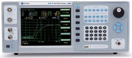
The Boonton 4500C RF Peak Power Analyzer is a dual-channel benchtop instrument designed for capturing, displaying, analyzing and characterizing microwave and RF power in both the time and statistical domains. The instrument provides two peak power sensor measurement channels and two trigger/oscilloscope channels, with a frequency range of 30 MHz to 40 GHz when paired with a compatible Boonton peak power sensor. The 4500C accepts pulse measurements from -50 dBm to +20 dBm and modulated measurements from -60 dBm to +20 dBm, providing greater than 80 dB of dynamic range without range switching.
Boonton positions the 4500C for design, verification, and troubleshooting of pulsed and noise-like signals used in commercial and military radar, electronic warfare, wireless communications including LTE, LTE-A, and 5G, consumer electronics including WLAN, as well as education and research applications. The instrument is intended for engineers working on the most demanding peak power measurement applications where time-domain resolution, statistical analysis of noise-like signals, and reliable capture of intermittent events all matter.
Boonton Electronics is a long-established American precision RF measurement brand specializing in RF power meters and modulation analyzers. The Boonton T&M business is part of Wireless Telecom Group, headquartered in Parsippany, New Jersey, which also includes the CommAgility, Microlab, and Noisecom brands.
The Boonton 4500C is the dual-channel benchtop RF Peak Power Analyzer in the Boonton 4500-series platform. It is configured as a standalone instrument that accepts two Boonton peak power sensors plus two trigger/oscilloscope channels, with a frequency range that depends on the sensor selected and extends up to 40 GHz with the appropriate sensor.
The 4500C ships as a dual-channel front-panel-input configuration by default, with rear-panel input and several functional options available. Within this product page, the configuration choices below describe how the same base instrument can be ordered with different I/O placement, statistical capability, storage architecture, and remote interface.
Each pre-owned 4500C below is its own dedicated product page with condition-matched pricing and the configuration options specified in the listing. Review the option codes carefully — the rear-panel input configuration, statistical package, removable SSD, and GPIB option each change the instrument's physical and functional behavior.
The primary configuration differences within the 4500C product line are I/O placement and installed options rather than measurement performance. Option 4500C-003 relocates the dual sensor inputs from the front panel to the rear panel, which is the typical choice for rack-integrated automated test systems. Option 4500C-006 adds dual trigger outputs on the rear panel, and Option 4500C-007 adds a rear-panel calibrator output.
Functional options change measurement capability rather than I/O. Option 4500C-010 adds the Statistical Package with gated CCDF and PDF, which is the option needed for noise-like signal characterization such as OFDM, WLAN, and modern wireless waveforms. Option 4500C-015 replaces the internal SSD with a removable SSD for environments with data-handling requirements, and Option 4500C-016 adds internally installed GPIB control for legacy automated test integration.
| Model | Frequency Range | Risetime | Description |
|---|---|---|---|
| 4500C | 30 MHz to 40 GHz | < 5 ns | Dual Channel, Front Panel Input |
Additional differences in specifications beyond the few shown above are not listed here — see each model's full specifications below.
| Sensor Inputs | |
|---|---|
| RF Frequency Range | 30 MHz to 40 GHz |
| Pulse Measurement Range | -50 to +20 dBm |
| Modulated Measurement Range | -60 to +20 dBm |
| Relative Offset Range | ±100.00 dB |
| Logarithmic Vertical Scale | 0.1 to 50 dBm/div, dBV/div, dBmV/div, dBuV/div in 1-2-5 sequence |
| Linear Vertical Scale | 1 nW/div to 50 MW/div; 1 mV/div to 50 kV/div in 1-2-5 sequence |
| Video Bandwidth | 125 MHz |
| Rise-Time | <5 ns |
| Single-Shot Bandwidth | 35 MHz |
| Pulse Repetition Rate | 50 MHz max |
| Minimum Pulse Width | 6 ns |
| Time Base | |
| Time Base Range | 5 ns/div to 1 hr/div |
| Time Base Accuracy | +/- 4 ppm peak |
| Time Base Resolution | 100 ps |
| Time Base Display | Sweeping or roll mode |
| Statistical X-Axis (optional) | |
| Scale | Linear or logarithmic, 1 to 7 cycles |
| Linear Ranges | 0.1%/div to 10%/div |
| Linear Offset | 0 to 99.9%, 0.1% resolution |
| Log Range | 1e-9% to 100% |
| Calibration Source | |
| Operating Modes | CW, internal or external pulse |
| Frequency | 1.024 GHz ± 0.01% |
| Level Range | -50 to +20 dBm |
| Resolution | 0.1 dB |
| Output VSWR | 1.10 maximum |
| Absolute Accuracy | ±0.04 dB (±0.9%) at 0 dBm |
| Accuracy vs Level | add ±0.02 dB per 5 dB increment from 0 dBm |
| Preset Internal Pulse Period | 0.1 or 1 or 10 ms |
| Preset Internal Pulse Duty Cycle | 10% to 90% in 10% increments |
| Variable Pulse On Time | 7 µsec to 65.535 ms in 1 µsec steps |
| Variable Pulse Period | 28 µsec to 131.070 ms in 2 µsec steps (off-time limits within 7 µsec to 65.535 ms) |
| Pulse Polarity | + or – |
| RF Connector | Precision Type N |
| External Pulse Input | Rear panel BNC, TTL level compatible |
| Measurement System | |
| Sensor Inputs | Two peak power sensor measurement channels and two trigger/oscilloscope channels |
| Measurement Technique | Random interleaved and real-time sampling system with pre- and post-trigger data and statistical histogram accumulation |
| Maximum Sampling Rate | 100 MS/s on up to four channels simultaneously (equivalent effective sampling rate of 10 GS/s with Random Interleaved Sampling) |
| Waveform Averaging | 1 to 16,384 samples per data point (time domain measurement) |
| Number of Histogram Bins | 16,384 |
| Size of Sample Bins | 32-bits (4,096 mega-samples) |
| Bin Power Resolution | <0.02 dB |
| Statistical Acquisition (optional) | |
| Modes | Continuous or gated by pulse mode time markers |
| Sampling Rate | 100 MS/s on all channels simultaneously |
| Limit Count | Adjustable, 2 to 4096 Megasamples |
| Limit Time | 3600 seconds (approx. 41 s at full sample rate) |
| Terminal Action | Stop, flush and restart or decimate |
| Trigger | |
| Trigger Source | Channel 1 (internal), Channel 2 (internal), External trigger 1, External trigger 2 |
| Trigger Slope | + or – |
| Trigger Delay Range | pre-trig(-), post-trig(+); 5 ns to 500 ns/div: -4 ms to +100 ms; 1 µs to 10 ms/div: ±4000 divisions; 20 ms to 3600 s/div: -40 to +100 s |
| Trigger Delay Resolution | 0.02 divisions |
| Trigger Hold-off Range | 0.0 to 1.0 s |
| Trigger Hold-off Resolution | 10 ns |
| Trigger Mode | Normal, auto, auto peak-to-peak, free run |
| B Trigger Mode | A only, B delay-by-time, B delay-by-events |
| B Trigger Source | Chan 1, Chan 2, Ext trig 1, Ext trig 2 |
| B Trigger Slope | + or – |
| B Trigger Events Counter Range | 1 to 999,999 events |
| B Trigger Time Delay Range | 0.0 to 1.0 s |
| B Trigger Time Delay Resolution | 10 ns |
| Internal Trigger Level Range | -40 to +20 dBm (sensor-dependent) |
| External Trigger Level Range | ±5 volts, ±50 volts |
| External Trigger Input | 1M or 50 ohm, DC Coupled |
| External Interfaces | |
| GPIB (optional) | Programmable interface; complies with SCPI ver. 1990 |
| USB | General purpose I/O interface |
| LAN | Ethernet port |
| Other Characteristics | |
| Display | 8.4" Diagonal TFT color LCD, 800 x 600 pixels, with LED backlight |
| Storage | Internal SSD ≥60GB; optional removable drive |
| Acquisition Engine | Real-Time Power Processing™ |
| Environmental | |
| Operating Temperature | 0 °C to 50 °C |
| Storage Temperature | -20 °C to 70 °C |
| Operating Humidity | 15 to 95% RH, non-condensing |
| Storage Humidity | 0 to 90% RH, non-condensing |
| Operating Altitude | 10,000 ft max (3048 m) |
| Storage Altitude | 50,000 ft max (15,240 m) |
| Regulatory |
Please review the Manufacturer's Data Sheet to verify published specifications. Feedback on this webpage is always welcome — please reach out to your Test Architect at any time for questions or concerns. Thank you, we truly appreciate you being our customer.
Model No
Boonton
Condition
Used
Manufacturer
Boonton

30+ Years in Business
Secure Payments
Sell Test Equipments
Knowledgeable Staff
On-site Lab
30+ Years in Business
Secure Payments
Sell Test Equipments
Knowledgeable Staff
On-site Lab
Request A Quote
 Chat Live
 Contact Us
 sales@valuetronics.com


