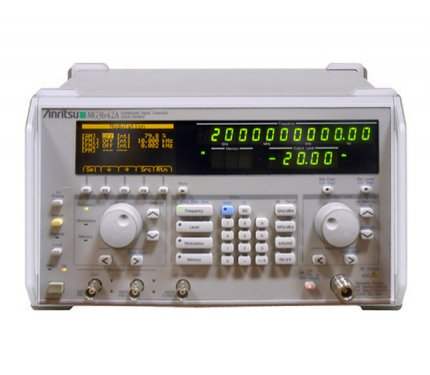
The Anritsu MG3641A and MG3642A are synthesized signal generators covering 125 kHz to 1040 MHz and 125 kHz to 2080 MHz respectively. Built around a low-noise YIG oscillator and Anritsu synthesizer technology, these instruments deliver 0.01 Hz frequency resolution across the full range, with non-harmonic spurious better than -100 dBc and SSB phase noise better than -130 dBc/Hz at 1 GHz with 20 kHz offset.
These signal generators are used as sources for interference testing of radio receivers and as local and reference signal sources. The instrument set supports mixer characteristic measurements using Frequency Only Mode with frequency offset, and amplifier IM3 measurements using Level Only Mode where two linked units feed a two-signal characteristics measurement pad driving the amplifier under test into a spectrum analyzer.
Anritsu Corporation is a Japanese precision measurement company with roots tracing to 1895. In 1990 Anritsu acquired Wiltron Company, a US-based RF and microwave instrument maker, consolidating signal generator and network analyzer product lines under the Anritsu name. The MG synthesized signal generator series has remained an Anritsu-branded product family across this corporate evolution.
The MG3641A and MG3642A share a common platform — identical synthesizer architecture, identical YIG oscillator design, identical modulation capability, and identical control and interface features. The two models differ in a single dimension: the upper frequency limit of the carrier. Both cover the same 125 kHz lower boundary, the same 0.01 Hz resolution, and the same +17 dBm standard output capability.
Anritsu offers this two-model arrangement so a buyer can select frequency coverage to match the application without paying for range that will not be used. Customers focused on cellular and lower-UHF bands can specify the MG3641A; customers needing coverage into the lower L-band region can specify the MG3642A. The option set — Option 01 reference oscillator, Option 11 pulse modulator, Option 21 AF synthesizer, Option 22 FSK encoder — applies identically to both models.
Each pre-owned model below has its own product page with condition-matched pricing and stock status. Where the MG3641A and MG3642A share a specification (resolution, signal purity at common frequencies, modulation capability, GPIB control set), the entries on each page reflect that. Where they differ — the upper frequency limit and the phase noise specification above 1040 MHz — the per-model page documents the specifics for that unit.
The MG3641A covers 125 kHz to 1040 MHz. The MG3642A covers 125 kHz to 2080 MHz. The comparison table that follows details the frequency boundary and the additional phase noise specification that applies to the MG3642A above 1040 MHz. For applications confined to sub-GHz and the lower 1 GHz region, the MG3641A is sufficient.
FM deviation ranges also scale with carrier frequency on both models, and the MG3642A adds an upper deviation range of 0 to 2048 kHz that is available only above 1040 MHz. Pulse modulation, AF synthesizer, and FSK encoder options are interchangeable between the two models. The user interface, sweep modes, memory capacity, and trigger sequence programming are identical.
| Model | Frequency Range | Output Level Range | Resolution |
|---|---|---|---|
| MG3642A | 125 kHz to 2080 MHz | -143 to +17 dBm (settable: -143 to +23 dBm) | 0.01 Hz |
| MG3641A | 125 kHz to 1040 MHz | -143 to +17 dBm (settable: -143 to +23 dBm) | 0.01 Hz |
Additional differences in specifications beyond the few shown above are not listed here — see each model's full specifications below.
| Parameter | Specification |
|---|---|
| Carrier Frequency | |
| Range | 125 kHz to 1040 MHz (MG3641A); 125 kHz to 2080 MHz (MG3642A) |
| Resolution | 0.01 Hz |
| Accuracy | Reference oscillator accuracy; reference oscillator accuracy ±(0.3% of FM setting deviation + 5 Hz) at frequency modulation |
| Internal Reference Oscillator Frequency | 10 MHz |
| Aging Rate | ±5 x 10⁻⁹/day |
| Start-up Characteristics | 1 x 10⁻⁷/10 min (for 24 h after power on) |
| Temperature Stability | ±3 x 10⁻⁸ (0° to 50°C) |
| External Reference Input | 5/10 MHz, ±10 ppm, ≥0.7 Vp-p/50 Ω (AC coupling), BNC connector (rear panel) |
| Buffer Output | 10 MHz, TTL level (DC coupling), BNC connector (rear panel) |
| Switching Time | ≤40 ms (external control, response time from last command until becomes within ±0.1 ppm of set frequency) |
| Output | |
| Range | -143 to +17 dBm (settable range: -143 to +23 dBm) |
| Units | dBm, dBµ, V, mV, µV (dBµ, V, mV and µV switchable between termination voltage display and open voltage display) |
| Resolution | 0.01 dB |
| Frequency Characteristics (at 0 dBm) | ±0.5 dB, ±1.0 dB (pulse modulation: on) |
| Accuracy | ±1 dB (-127 to +17 dBm, upper limit at pulse modulation: +12 dBm), ±3 dB (≤-127 dBm) |
| Impedance | 50 Ω (N connector), VSWR: ≤1.5 (≤-3 dB), ≤2.5 (>-3 dB) |
| Switching Time | ≤50 ms (normal mode), ≤100 ms (level safety mode), ≤10 ms (continuous mode) |
| Continuous Mode | Variable within set value ±10 dB with no interruption of output |
| Safety Mode | Prevent spike signal generation when operating mechanical-type attenuator |
| Interference Radiation | ≤0.1 µV (at output frequency), ≤1 µV (over entire frequency range, multi-menu display: OFF) |
| Signal Purity (CW mode, ≤+7 dBm) | |
| Harmonics | ≤-30 dBc (2nd, 3rd) |
| Non-harmonic | ≤-100 dBc (≥15 kHz offset) |
| Those Related Power | ≤-40 dBc (<15 kHz offset) |
| SSB Phase Noise (CW Mode, 20 kHz offset) | ≤-140 dBc/Hz (10 to <256 MHz), ≤-136 dBc/Hz (256 to <512 MHz), ≤-130 dBc/Hz (512 to 1040 MHz), ≤-124 dBc/Hz (>1040 MHz, MG3642A only) |
| Residual AM (CW mode) | ≤-80 dBc (≥500 kHz, CW mode, +7 dBm, 50 Hz to 15 kHz demodulation band) |
| Residual FM (CW mode, 300 Hz to 3 kHz) | <4 Hzrms (10 to <512 MHz), <8 Hzrms (512 to 1040 MHz), <16 Hzrms (>1040 MHz, MG3642A only) |
| Residual FM (CW mode, 50 Hz to 15 kHz) | <5 Hzrms (10 to <512 MHz), <10 Hzrms (512 to 1040 MHz), <20 Hzrms (>1040 MHz, MG3642A only) |
| Amplitude Modulation | |
| Range | 0% to 100% |
| Resolution | 0.1% |
| Accuracy | ±(5% of set value + 2%) at ≥0.4 MHz, ≤+7 dBm, ≤90% AM, source: Int 1 (1 kHz), 300 Hz to 3 kHz demodulation band |
| Modulation Frequency Response (output: ≤+7 dBm) | See modulation frequency response table in datasheet |
| Distortion | ≤-40 dB (30% AM), ≤-30 dB (90% AM) at ≥0.4 MHz, ≤+7 dBm, source: Int 1 (1 kHz) |
| Incidental FM | <200 Hz peak at ≥0.4 MHz, AM: 30%, ≤+7 dBm, source: Int 1 (1 kHz), 300 Hz to 3 kHz demodulation band |
| Modulation Signal Source | One of internal (Int 1, Int 2, Int 3) and external (Ext 1, Ext 2) |
| Modulation Signal Polarity | Positive/negative switchable |
| Frequency Modulation | |
| Range | 0 to 125 Hz (125 to <250 kHz) up to 0 to 2048 kHz (>1040 MHz, MG3642A only) |
| Resolution | 1 Hz (0 to 4 kHz deviation) up to 1 kHz (1025 to 2048 kHz deviation, MG3642A only) |
| Accuracy | ±(5% of set value + 10 Hz) at 0.4 to <512 MHz, ±(5% of set value + 20 Hz) at 512 to 1040 MHz, ±(5% of set value + 40 Hz) at >1040 MHz (MG3642A only); Source: Int 1 (1 kHz), 300 Hz to 3 kHz demodulation band |
| Modulation Frequency Response | DC or 20 Hz to 20 kHz (0.4 to <10 MHz), DC or 20 Hz to 100 kHz (≥10 MHz) at ±1 dB bandwidth |
| Distortion | ≤-40 dB at ≥16 MHz, 3.5 kHz deviation, source: Int 1 (1 kHz); ≤-45 dB at ≥64 MHz, 22.5 kHz deviation, source: Int 1 (1 kHz) |
| Incidental FM | <1% peak at ≥64 MHz, ≤+7 dBm, 100 kHz deviation, source: Int 1 (1 kHz), 300 Hz to 3 kHz demodulation band |
| External Modulation Group Delay | <30 µs at ≥10 MHz, source: external DC coupling mode, modulation rate: ≤100 kHz |
| Modulation Signal Source (FM1, FM2) | One of internal (Int 1, Int 2, Int 3), and external (Ext 1, Ext 2) |
| Modulation Signal Polarity | FM1, FM2 positive/negative switchable |
| Pulse Modulation | |
| Specifications | According to option specifications (Option 11) |
| Modulation Signal Source | |
| Internal Modulation (Int 1) Frequency | 400 Hz, 1 kHz |
| Internal Modulation (Int 1) Accuracy | Same as reference oscillator accuracy |
| Internal Modulation (Int 2, Int 3) | According to option specifications |
| External Modulation (Ext 1, Ext 2) Proper Input Level | 2 Vp-p approx. |
| External Modulation Input Impedance | 600 Ω, BNC connector |
| External Modulation Coupling | DC/AC switchable |
| AF Output | |
| Output Signal Source | One of internal (Int 1, Int 2, Int 3) and external (Ext 1, Ext 2) |
| Output Level | 0 to 4 Vp-p |
| Output Level Resolution | 1 mVp-p |
| Output Level Accuracy | ±(5% of setting level + 2 mVp-p), Source: Int 1 (1 kHz) |
| Impedance | 600 Ω, BNC connector |
| Simultaneous Modulation | |
| Capability | Excluding amplitude modulation and pulse modulation combination, simultaneous modulation, modulation rate, deviation independently settable |
| Sweep Function | |
| Sweep Parameters | Frequency, output level, memory |
| Frequency Sweep (start/stop) | Linear (specified step size and number of points), Log (multiplying factor: 1%) |
| Frequency Sweep (center/span) | Linear (specified step size and number of points) |
| Level Sweep (start/stop, center/span) | dB (specified step size and number of points); Sweep: continuous mode (max. 20 dB width) |
| Memory Sweep | Start/stop |
| Sweep Mode | Auto, single, manual |
| Sweep Time Setting Range | 1 ms to 600 s/point (actual sweep time depends on sweep parameter) |
Please review the Manufacturer's Data Sheet to verify published specifications. Feedback on this webpage is always welcome — please reach out to your Test Architect at any time for questions or concerns. Thank you, we truly appreciate you being our customer.
Model No
Anritsu
Condition
Used
Manufacturer
Anritsu
Frequency
2.08 GHz

30+ Years in Business
Secure Payments
Sell Test Equipments
Knowledgeable Staff
On-site Lab
30+ Years in Business
Secure Payments
Sell Test Equipments
Knowledgeable Staff
On-site Lab
Request A Quote
 Chat Live
 Contact Us
 sales@valuetronics.com