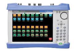
The Anritsu Cell Master MT8212E and MT8213E are compact, lightweight handheld Base Station Analyzers designed for the installation and maintenance of wireless networks. Anritsu positions the Cell Master as a base station analyzer meeting virtually all the testing needs of an RF technician, combining a cable and antenna analyzer, a spectrum and interference analyzer, and a power meter in a single instrument, with Signal Analyzer options for 2G, 3G, and 4G cellular networks including LTE, WiMAX, and digital broadcast.
A handheld base station analyzer brings several bench-class measurement functions into one field-portable unit so a technician can characterize a site without carrying separate instruments. The Cell Master is built around installation and maintenance tasks for wireless networks: line-sweeping feedlines and antennas, spectrum and interference work, coverage and interference mapping, EMF field-strength testing, T1/E1/T3 backhaul analysis, and digital broadcast measurement for ISDB-T and DVB-T/H. GPS information can be stored with traces for location-referenced results.
ValueTronics stocks and holds its own inventory in a 20,000-square-foot secure warehouse at 1675 Cambridge Drive in Elgin, Illinois. Every used unit we sell is inspected and functionally verified in-house before it ships, while new units ship factory-sealed exactly as received from the manufacturer, so you know the condition of what arrives on your bench.
The Anritsu Cell Master is a compact, lightweight handheld Base Station Analyzer family built for the installation and maintenance of wireless networks. It combines a cable and antenna analyzer, a spectrum and interference analyzer, and a power meter in a single instrument designed to meet virtually all the testing needs of an RF technician working in the field.
The series spans two models, the MT8212E and the MT8213E, which share the same measurement architecture and differ primarily in their upper frequency limit. Both can be expanded with Signal Analyzer options covering 2G, 3G, and 4G standards including LTE/LTE-A, GSM/EDGE, W-CDMA/HSPA+, TD-SCDMA, CDMA, EV-DO, and WiMAX, as well as ISDB-T and DVB-T/H digital broadcast and T1/E1/T3 backhaul analysis.
Each model below links to its own dedicated pre-owned product page with condition-matched pricing. Select the model whose frequency coverage and installed options match your application, then choose the listing that fits your budget and availability.
The core distinction between the two models is frequency range. The MT8212E covers cable and antenna measurements from 2 MHz to 4 GHz, spectrum analysis from 9 kHz to 4 GHz, and power metering from 10 MHz to 4 GHz. The MT8213E extends each of those functions to a 6 GHz ceiling: 2 MHz to 6 GHz for cable and antenna work, 9 kHz to 6 GHz for spectrum analysis, and 10 MHz to 6 GHz for the power meter.
Beyond frequency coverage, the two models share the same touchscreen display, calibration methods, connectivity, and option list. The comparison table below summarizes the frequency tiers so you can match the instrument to the bands you need to test.
| Model | Cable & Antenna Analyzer Range | Spectrum Analyzer Range | Power Meter Range |
|---|---|---|---|
| MT8213E | 2 MHz to 6 GHz | 9 kHz to 6 GHz | 10 MHz to 6 GHz |
| MT8212E | 2 MHz to 4 GHz | 9 kHz to 4 GHz | 10 MHz to 4 GHz |
Additional differences in specifications beyond the few shown above are not listed here — see each model's full specifications below.
| Specification | Value |
|---|---|
| Cable and Antenna Analyzer | |
| Frequency Range | 2 MHz to 6 GHz |
| Frequency Accuracy | ≤ ± 2.5 ppm @ 25 ºC |
| Frequency Resolution | 1 kHz (RF immunity low), 100 kHz (RF immunity high) |
| Output Power (High) | 0 dBm, typical |
| Output Power (Low) | –30 dBm, typical |
| Interference Immunity (On-Channel) | +17 dBm @ > 1.0 MHz from carrier frequency |
| Interference Immunity (On-Frequency) | 0 dBm within ± 10 kHz of the carrier frequency |
| Measurement Speed (Return Loss) | ≤ 1.00 ms/data point, RF immunity low, typical |
| Measurement Speed (Distance-to-Fault) | ≤ 1.25 ms/data point, RF immunity low, typical |
| Return Loss Measurement Range | 0 dB to 60 dB (Resolution 0.01 dB) |
| VSWR Measurement Range | 1:1 to 65:1 (Resolution 0.01) |
| Cable Loss Measurement Range | 0 dB to 30 dB (Resolution 0.01 dB) |
| Distance-to-Fault Horizontal Range | 0 to (Data Points–1) x Fault Resolution, maximum 1500 m (4921 ft) |
| 1-Port Phase Range | –180º to +180º (Resolution 0.01º) |
| Directivity (Corrected) | > 42 dB OSL Calibration; > 38 dB InstaCal Calibration |
| Data Points | 137, 275, 551, 1102, 2204 |
| 2-Port Transmission Measurement (Option 21) | |
| High Dynamic Range (On), 2 MHz to 4 GHz | 80 dB, 95 dB, typical |
| High Dynamic Range (On), 4 GHz to 6 GHz | 70 dB, 85 dB, typical |
| Bias-Tee (Option 10) | |
| Voltage Range | +12 V to +32 V |
| Current (Low/High) | 250 mA / 450 mA, 1 A surge for 100 ms |
| Resolution | 0.1 V |
| Spectrum Analyzer | |
| Frequency Range | 9 kHz to 6 GHz |
| Tuning Resolution | 1 Hz |
| Frequency Reference Aging | ± 1.0 ppm/year |
| Frequency Reference Accuracy | ± 1.5 ppm (25 °C ± 25 °C) + aging, < ± 50 ppb with GPS On |
| Frequency Span | 10 Hz to 6 GHz including zero span |
| Sweep Time | Minimum 100 ms; 10 µs to 600 s in zero span |
| Sweep Time Accuracy | ± 2 % in zero span |
| Resolution Bandwidth (RBW) | 1 Hz to 3 MHz in 1–3 sequence ± 10% (1 MHz max in zero-span) (–3 dB bandwidth) |
| Video Bandwidth (VBW) | 1 Hz to 3 MHz in 1–3 sequence (–3 dB bandwidth) |
| SSB Phase Noise @ 1 GHz (10 kHz offset) | –100 dBc/Hz, –110 dBc/Hz typical |
| SSB Phase Noise @ 1 GHz (100 kHz offset) | –105 dBc/Hz, –112 dBc/Hz typical |
| SSB Phase Noise @ 1 GHz (1 MHz offset) | –115 dBc/Hz, –121 dBc/Hz typical |
| Dynamic Range | > 102 dB (2.4 GHz), 2/3 (TOI-DANL) in 1 Hz RBW |
| Measurement Range | DANL to +26 dBm (≥ 50 MHz); DANL to 0 dBm (< 50 MHz) |
| Display Range | 1 dB to 15 dB/div in 1 dB steps, ten divisions displayed |
| Reference Level Range | –120 dBm to +30 dBm |
| Maximum Continuous Input Power | +30 dBm |
| Attenuator Range | 0 dB to 55 dB in 5 dB steps |
| Amplitude Accuracy (9 kHz to 100 kHz) | ± 2.00 dB typical (Preamp Off) |
| Amplitude Accuracy (100 kHz to 4.0 GHz) | ± 1.25 dB, ± 0.5 dB typical |
| Amplitude Accuracy (> 4.0 GHz to 6 GHz) | ± 1.50 dB, ± 0.5 dB typical |
| Residual Spurious | < –90 dBm (RF input terminated, 0 dB attenuation, > 10 MHz) |
| Input-Related Spurious | < –75 dBc (0 dB attenuation, –30 dBm input, span < 1.7 GHz, carrier offset > 4.5 MHz) |
| Third-Order Intercept (TOI), 800 MHz | +16 dBm |
| Third-Order Intercept (TOI), 2400 MHz | +20 dBm |
| Third-Order Intercept (TOI), 200 MHz to 2200 MHz | +25 dBm, typical |
| Third-Order Intercept (TOI), > 2.2 GHz to 5.0 GHz | +28 dBm, typical |
| Third-Order Intercept (TOI), > 5.0 GHz to 6.0 GHz | +33 dBm, typical |
| Second Harmonic Distortion (50 MHz) | –56 dBc |
| VSWR | 2:1, typical |
| Displayed Average Noise Level (DANL) (RBW = 1 Hz, 0 dB attenuation) | |
| 10 MHz to 2.4 GHz | Preamp Off: –141 dBm max, –146 dBm typical; Preamp On: –157 dBm max, –162 dBm typical |
| > 2.4 GHz to 4 GHz | Preamp Off: –137 dBm max, –141 dBm typical; Preamp On: –154 dBm max, –159 dBm typical |
| > 4 GHz to 5 GHz | Preamp Off: –134 dBm max, –138 dBm typical; Preamp On: –150 dBm max, –155 dBm typical |
| > 5 GHz to 6 GHz | Preamp Off: –126 dBm max, –131 dBm typical; Preamp On: –143 dBm max, –150 dBm typical |
| Power Meter | |
| Frequency Range | 10 MHz to 6 GHz |
| Span | 1 kHz to 100 MHz |
| Display Range | –140 dBm to +30 dBm, ≤ 40 dB span |
| Measurement Range | –120 dBm to +26 dBm |
| Offset Range | 0 dB to +100 dB (External Gain or Loss) |
| VSWR | 2:1 typical |
| Maximum Continuous Input Power | +30 dBm |
| General Specifications | |
| Internal Trace/Setup Memory | 2,000 traces, 2,000 setups |
| Display Type | Resistive Touchscreen |
Important: RF input damage level: +33 dBm peak, +/- 50 VDC. Maximum continuous input power: +30 dBm (>= 10 dB attenuation).
Important: GPS Receiver (Option 31): the GPS antenna is sold separately.
Important: High-Accuracy Power Meter (Option 19) requires an external USB Power Sensor (sold separately; e.g., MA24105A, MA24106A, MA24108A/18A/26A, MA24208A/18A).
Important: CW Signal Generator (Option 28) requires the CW Signal Generator Kit, P/N 69793 (sold separately).
Important: EMF Measurements (Option 444) requires an Anritsu Isotropic Antenna (sold separately; e.g., 2000-1791-R, 2000-1792-R, 2000-1800-R).
Important: Coverage Mapping (Option 431) requires Option 31 (GPS Receiver).
Important: Recommended calibration cycle is 12 months.
Recommended pairing: the Interference Analyzer (Option 25) supports the Anritsu MA2700A Handheld Interference Hunter for locating and direction-finding interfering signals in the field.
This pre-owned unit is inspected and functionally verified in-house before it ships and is backed by our pre-owned warranty. To confirm its exact condition, firmware revision, installed options, or included accessories for your application before ordering, contact our Test Architects.
ValueTronics supplies both new and used test and measurement equipment. New units ship factory-sealed, exactly as received from the manufacturer; every used unit is inspected and functionally verified in-house at our 20,000 sq ft secure facility in Elgin, Illinois before it ships. Our Test Architects can help you select the condition, calibration, and configuration that fit your application.
Please review the Manufacturer's Data Sheet to verify published specifications. Feedback on this webpage is always welcome — please reach out to your Test Architect at any time for questions or concerns. Thank you, we truly appreciate you being our customer.
Model No
Anritsu
Condition
Pre-Owned
Manufacturer
Anritsu
Cabant_ana_freq
2 MHz to 6 GHz
Spec_ana_freq
9 kHz to 6 GHz

30+ Years in Business
Secure Payments
Sell Test Equipments
Knowledgeable Staff
On-site Lab
30+ Years in Business
Secure Payments
Sell Test Equipments
Knowledgeable Staff
On-site Lab
Request A Quote
 Chat Live
 Contact Us
 sales@valuetronics.com