Chat Live
 Contact Us
 sales@valuetronics.com


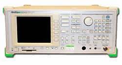
The MS2602A is a high-performance spectrum analyzer covering 100 Hz to 8.5 GHz, designed for the expanded use of frequencies in the quasi-microwave band and for increasingly digitized radio equipment. It combines high signal purity, low distortion, and high measurement accuracy with time-domain and burst-measurement capability in a single instrument.
Its frequency coverage reaches the third-to-fifth harmonic range of digital cordless telephones at 1.9 GHz and of digital car, portable, and private mobile telephones at 1.5 GHz, supporting accurate evaluation of high-performance radio equipment and electronic parts over a wide dynamic range. Time-domain and burst-measurement functions allow analysis of burst signals used in time-division-multiplex (TDM) digital radio communication systems, and the adjacent channel leakage power function addresses the wide channel separation of digital mobile communications equipment.
ValueTronics stocks and holds its own inventory in a 20,000 square-foot secure warehouse at 1675 Cambridge Drive in Elgin, Illinois, so the instruments listed here are equipment we keep on hand. Every order is backed by our in-house team: each used unit is inspected and functionally verified by our technicians before it ships, while new units ship factory-sealed exactly as received.
| Specification | Value |
|---|---|
| Frequency | |
| Frequency range | 100 Hz to 8.5 GHz |
| Frequency band structure | Band 0 (0 to 2 GHz), band 1– (1.7 to 7.5 GHz), band 1+ (6.5 to 8.5 GHz) |
| Pre-selector frequency range | 1.7 to 8.5 GHz |
| Frequency setting range | 100 Hz to 8.5 GHz (band 1–, 1+) |
| Frequency setting mode | CENTER-SPAN, START-SPAN, START-STOP |
| Frequency setting resolution | 1 Hz |
| Display frequency resolution | 1/1000 digit of span (min. 1 Hz), fractions are rounded |
| Display frequency accuracy | ±(display frequency x reference frequency accuracy + span x span accuracy) |
| Marker frequency resolution | 0.2% of span, fractions are rounded |
| Marker frequency accuracy | Same as display frequency accuracy (NORMAL), same as span accuracy (DELTA) |
| Frequency measurement resolution | 1 Hz, 10 Hz, 100 Hz, 1 kHz |
| Frequency measurement accuracy | Display frequency x reference frequency accuracy ±1 count (S/N ≥20 dB) |
| Span setting range | 0 Hz, 100 Hz to 8.5 GHz |
| Span setting resolution | Ten-key/data knob: 3-digit value (100 to 999), step key: 1-2-5 sequence |
| Span accuracy | ±2.5% (span ≥1 kHz), ±5% (100 Hz ≤span <1 kHz) |
| Resolution bandwidth setting range | 10 Hz to 3 MHz (3 dB), 1-3 sequence (manual or auto by span) |
| Resolution bandwidth accuracy | ±20% |
| Resolution bandwidth selectivity (60 dB/3 dB) | ≤15:1 (100 kHz to 3 MHz), ≤12:1 (10 Hz to 30 kHz) |
| Video bandwidth | 1 Hz to 3 MHz, 1-3 sequence (manual or auto by RBW), OFF |
| Sideband noise | ≤–105 dBc/Hz (10 kHz offset), ≤–115 dBc/Hz (50 kHz offset), ≤–120 dBc/Hz (100 kHz offset) at frequency of 1 MHz to 4 GHz |
| Power spurious | ≤–60 dBc (frequency ≤1 GHz, offset <360 Hz), ≤–70 dBc (frequency ≤1 GHz, offset ≥360 Hz) |
| Residual FM | ≤2 Hzp-p/0.1 s (frequency ≤1 GHz, span 0 Hz) |
| Frequency drift | ≤20 Hz/min (span ≤1 kHz), ≤200 Hz/min (span ≤10 kHz) |
| Reference oscillator frequency | 10 MHz |
| Reference oscillator start-up characteristics | ≤5 x 10⁻⁸ (after 10-min warm-up, vs. 24-hour warm-up); Option 01: ≤2 x 10⁻⁸ (after 30-min warm-up) |
| Reference oscillator aging rate | ≤2 x 10⁻⁸/day (option 01: ≤5 x 10⁻⁹/day), ≤1 x 10⁻⁷/year (option 01: ≤5 x 10⁻⁸/year) |
| Reference oscillator temperature characteristics | ±5 x 10⁻⁸ (0° to 50°C), option 01: ±3 x 10⁻⁸ (0° to 50°C) |
| Amplitude | |
| Level measurement range | Average noise level to +30 dBm |
| Maximum input | Average CW power: +30 dBm (input ATT ≥5 dB), DC power: 0 Vdc |
| Average noise level | ≤–135 dBm (1 MHz to 1.7 GHz), ≤–135 dBm (1.7 to 7.5 GHz), ≤–130 dBm (7.5 to 8.5 GHz) [at RBW 10 Hz, VBW 1 Hz, input ATT 0 dB] |
| Residual response | ≤–100 dBm (1 MHz to 8.5 GHz, input ATT 0 dB) |
| Total level accuracy | ±1.1 dB (100 Hz to 2 GHz), ±1.6 dB (2 to 8.5 GHz) |
| Reference level setting range | LOG: –100 to +30 dBm (or equivalent level), LIN: 22.4 µV to 7.07 V |
| Reference level setting resolution | 0.1 dB (or equivalent level) |
| Level step setting range | 0.1 to 100.0 dB |
| Unit | LOG: dBm, dBµV, dBmV, V, dBµV (emf), W; LIN: V |
| Reference level accuracy | ±0.3 dB (–50 to 0 dBm), ±0.75 dB (–70 to –50 dBm, 0 to +30 dBm), ±1.5 dB (–90 to –70 dBm) |
| Resolution bandwidth switching deviation | ±0.3 dB (after calibration) |
| Log/linear scale switching deviation | ±0.3 dB (after calibration) |
| Input attenuator | 0 to 55 dB, in 5 dB steps (manual or auto by reference level) |
| Input ATT switching deviation | ±0.3 dB (at 100 MHz, referred to 10 dB) |
| Pulse digitization uncertainty | LOG: 1.2 dBp-p (RBW ≤1 MHz), 3 dBp-p (RBW 3 MHz); LIN: 4% of reference level (RBW ≤1 MHz), 12% of reference level (RBW 3 MHz) |
| Frequency characteristics (input ATT 10 dB, 18° to 28°C) | ±0.5 dB (100 Hz to 2 GHz, band 0), ±1 dB (1.7 to 8.5 GHz, band 1–, 1+) |
| Frequency characteristics (input ATT 5 to 55 dB) | ±1 dB (100 Hz to 2 GHz, band 0), ±1.5 dB (1.7 to 8.5 GHz, band 1–, 1+) |
| CRT display scale | 10 div (single scale); LOG: 10 dB, 5 dB, 2 dB, 1 dB /div; LIN: 10%, 5%, 2%, 1% /div |
| Linearity (after calibration) | LOG: ±0.3 dB (0 to –20 dB, RBW ≤1 MHz), ±1 dB (0 to –70 dB, RBW ≤100 kHz), ±1.5 dB (0 to –90 dB, RBW ≤10 kHz); LIN: ±3% (vs. reference level) |
| Marker level resolution | LOG: 0.01 dB, LIN: 0.01% (vs. reference level) |
| 1 dB gain compression | ≥–1 dBm (18° to 28°C, ≥100 MHz), ≥–3 dBm (0° to 50°C, ≥100 MHz) |
| Maximum dynamic range | 1 dB gain compression level to noise level: >134 dB (1 MHz to 7.5 GHz), >129 dB (7.5 to 8.5 GHz) |
| Distortion characteristics, 2nd harmonic | >87.5 dB (5 to 800 MHz), >92.5 dB (800 to 850 MHz), >107.5 dB (>850 MHz) |
| Distortion characteristics, 3rd mutual modulation | >93.3 dB (10 to 50 MHz), >98.3 dB (50 MHz to 2 GHz), >96.6 dB (2 to 7.5 GHz) |
| Sweep | |
| Sweep time setting | 20 ms to 1000 s (data point 501, two most significant digits); 50 to 1000 s (other cases) |
| Sweep time accuracy | ±10% (20 ms to 200 s), ±15% (200 to 1000 s) |
| Sweep mode | CONTINUOUS, SINGLE |
| Trigger switch | FREE RUN, TRIGGERED |
| Trigger source | VIDEO, LINE, EXT (±10 V), EXT (TTL), TV-H, TV-V |
| Gate mode | OFF, random sweep mode; GATE DELAY: 0 to 65.5 ms (1 µs unit), GATE LENGTH: 20 µs to 65.5 ms (1 µs unit, GATE END: INT), GATE END: INT/EXT |
| Zone sweep | Sweeps only in the range indicated by zone marker |
| Tracking sweep | Sweeps while tracing peak points within zone marker (zone sweep also possible) |
| Time domain waveform display | |
| Sweep time | 50, 100 to 900 µs (data point 501); 1 ms to 1000 s (501, two most significant digits); 100, 200 to 800 µs (1002); 1 ms to 1000 s (1002) |
| Sweep time accuracy | ±0.5% |
| Delay time setting range | Pre-trigger: –(minus) time span to 0 s (1-point unit); Post-trigger: 0 to 65.5 ms (1 µs unit) |
| Amplitude resolution | 50 µs to 49 ms, 10 bits A/D (0.1% of full-scale); 50 ms to 1000 s, 14 bits A/D (0.01% of full-scale) |
| Number of data points | NORMAL: 501 points, DOUBLE: 1002 points |
| Detection mode | POS PEAK, SAMPLE, NEG PEAK |
| CRT Display | |
| Size / color | 7-inch, Color: green |
| Waveform display | 501-point horizontal axis; 322-point vertical axis |
| Display functions | Trace A (frequency spectrum), Trace B (frequency spectrum), Trace Time (time domain at center frequency), Trace A/B (simultaneous), Trace A/BG (background + foreground via zone marker), Trace A/Time (spectrum + time domain at center frequency) |
| Storage display | NORMAL, VIEW, MAX HOLD, MIN HOLD, AVERAGE, CUMULATIVE, OVERWRITE |
| AM/FM Demodulation | |
| Audio output | Built-in loudspeaker, with earphone terminal |
| Frequency deviation measurement range | 2 kHz/div, 20 kHz/div, 200 kHz/div |
| Frequency deviation measurement resolution | 50 Hz, 500 Hz, 5 kHz |
| Demodulated frequency (3 dB bandwidth), AC mode | 50 Hz to 50 kHz, 50 Hz to 1 MHz |
| Demodulated frequency (3 dB bandwidth), DC mode | DC to 50 kHz, DC to 1 MHz |
| Input Connector | |
| Input connector | 50 Ω, N-type (receptacle), VSWR ≤1.5 (input ATT ≥5 dB) |
| Auxiliary Signal Input and Output | |
| 500 MHz OUTPUT | –18 dBm±3 dB (50 Ω termination, BNC connector) |
| 21.4 MHz IF OUTPUT | –10 dBm±2 dB (50 Ω termination, upper edge, BNC connector) |
Important: Maximum input: +30 dBm average CW power (input attenuator 5 dB or greater); DC power 0 V.
Important: Interference radiation (≤20 dBµV) can be measured on the front panel using the MA2601B EMI Probe (except the horizontal synchronous signal, which is whole-number multiples of 25 kHz). The MA2601B EMI Probe is not listed among the standard accessories and must be obtained separately for this measurement.
Important: PTA (Personal Test Automation) is an option (MS2602A-04/-05). The external PTA keyboard (MC3305A JIS type or MC3306A ASCII type) is required to edit programs and is included only with Option 04 (Option 05 is supplied without the external PTA keyboard).
This pre-owned unit is inspected and functionally verified in-house before it ships and is backed by our pre-owned warranty. To confirm its exact condition, firmware revision, installed options, or included accessories for your application before ordering, contact our Test Architects.
ValueTronics supplies both new and used test and measurement equipment. New units ship factory-sealed, exactly as received from the manufacturer; every used unit is inspected and functionally verified in-house at our 20,000 sq ft secure facility in Elgin, Illinois before it ships. Our Test Architects can help you select the condition, calibration, and configuration that fit your application.
Please review the Manufacturer's Data Sheet to verify published specifications. Feedback on this webpage is always welcome — please reach out to your Test Architect at any time for questions or concerns. Thank you, we truly appreciate you being our customer.
Model No
Anritsu
Condition
Pre-Owned
Manufacturer
Anritsu
Spec_ana_freq
100 Hz to 8.5 GHz


30+ Years in Business

Secure Payments

Sell Test Equipments

Knowledgeable Staff

On-site Lab
30+ Years in Business
Secure Payments
Sell Test Equipments
Knowledgeable Staff
On-site Lab
Request A Quote