Chat Live
 Contact Us
 sales@valuetronics.com


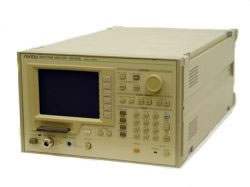
The Anritsu MS2601B/K is a wide-band spectrum analyzer covering 9 kHz to 2.2 GHz, spanning the video through VHF/UHF bands. A synthesized local oscillator together with automatic calibration from a built-in, highly accurate signal source enables accurate frequency and level measurement. Original functions such as the zone marker and scroll function shorten measurement time, and plug-in memory cards (PMCs) store measurement conditions and waveform data for repeatable operation.
The instrument is intended for measuring transmission quality such as spurious emissions from radio communication equipment, measuring electromagnetic interference (EMI), testing high-frequency parts such as RF converters and tuners, and measuring various devices such as filters and ICs. Each pressing of the CAL key recalibrates the analyzer against its internal signal source, so accurate measurements can be made even when the working temperature changes drastically.
ValueTronics stocks and holds its own test-and-measurement inventory in a 20,000 sq ft secure warehouse at 1675 Cambridge Drive in Elgin, Illinois, so the instruments we list are equipment we keep on hand. Every pre-owned order ships from that facility; each pre-owned unit is inspected and functionally verified in-house against the manufacturer's specifications before it leaves, while new units ship factory-sealed exactly as received.
The MS2601B/K is offered as two main-frame models that share the same 9 kHz to 2.2 GHz spectrum-analyzer architecture, automatic calibration, zone marker and scroll functions, and PMC memory-card operation. The models are distinguished primarily by their RF input: the MS2601B presents a 50 Ω input, and the MS2601K presents a 75 Ω input.
Both models accept the same option set, including PTA (Options 01/04), the RS-232C interface (Option 02), and the frequency-range extension to 100 Hz (Option 05), so the choice between them is driven mainly by the impedance and connector required for the device under test.
Each model below links to its own dedicated product page with condition-matched pricing for the pre-owned configuration you select. Choose the impedance variant that matches your application, then pick the condition and options on that model's page.
The two models differ in their RF input section. The MS2601B uses a 50 Ω input on an N-type connector with a DC maximum input level of ±50 V, while the MS2601K uses a 75 Ω input on an NC-type connector with a DC maximum input level of ±100 V; both share a +25 dBm RF maximum at input ATT ≥ 10 dB and VSWR ≤ 1.5.
Level-related figures such as average noise level, frequency response, and LOG measurement range carry separate values for the 50 Ω and 75 Ω inputs, and Option 05 extends each model's lower frequency limit to 100 Hz using the MA8601A (MS2601B) or MA8601J (MS2601K) DC block adapter. The comparison table that follows lists each model's specific values side by side.
| Model | Frequency Range | Input Impedance | Connector |
|---|---|---|---|
| MS2601B | 9 kHz to 2.2 GHz | 50 Ω | N-type |
| MS2601K | 9 kHz to 2.2 GHz | 75 Ω | NC-type |
Additional differences in specifications beyond the few shown above are not listed here — see each model's full specifications below.
| Specification | Value |
|---|---|
| Frequency | |
| Measurement frequency range | 9 kHz to 2.2 GHz |
| Frequency setting | 0 to 2210 MHz (stop frequency: ≥1 kHz) |
| Display resolution | 20 Hz |
| Setting mode | CENTER/SPAN, START/SPAN, START/STOP; set frequency span (stop freq. – start freq.) to 2-digit value (10 to 98) |
| Frequency display accuracy | ±(100 Hz + freq. span × 2% + display freq. × reference freq. accuracy), for CENTER/SPAN or START/SPAN mode after auto-calibration, provided freq. span ≥10 kHz and sweep time ≤100 s |
| Frequency span — setting range | 1 kHz to 2200 MHz for horizontal 10 divisions, 2-digit (10 to 98) variable, and 0 Hz (fixed tuning) |
| Frequency span — resolution | 1 kHz to 2000 MHz, 1-2-5 sequence at step keys |
| Frequency span — readout accuracy | ±2% (sweep time ≤100 s) |
| Resolution bandwidth | 30 Hz to 1 MHz (3 dB bandwidth), variable in 1-3 sequence, manual or automatically coupled to frequency span |
| Resolution bandwidth accuracy | ±20% |
| Selectivity | ≤15 : 1 (ratio of 60 dB and 3 dB bandwidth) |
| Stability — residual FM | ≤20 Hz p-p/0.1 s (frequency span ≤500 kHz) |
| Stability — drift | ≤300 Hz/min (frequency span ≤500 kHz, sweep time ≤100 s, after 1-hour warm-up at constant ambient temperature) |
| Sideband noise | ≤–80 dBc (at 100 Hz resolution bandwidth, 1 Hz video bandwidth, 10 kHz from signal) |
| Reference oscillator | |
| Frequency | 10 MHz |
| Stability — starting characteristic | Within ±5 × 10⁻⁸ (after 20-minute warm-up, referred to frequency after 1-hour warm-up) |
| Stability — aging rate | Within ±2 × 10⁻⁸/day, ≤1 × 10⁻⁷/year (referred to frequency after 24-hour warm-up) |
| Stability — temperature characteristic | Within ±5 × 10⁻⁸ (referred to frequency at 25°C) |
| External reference input | Frequency: 10 MHz, Level: 2 to 5 Vp-p |
| Markers | |
| Normal | Displays frequency at tunable marker; display accuracy same as center frequency display accuracy |
| Delta | Displays frequency difference between reference marker and tunable marker; display accuracy same as frequency span display accuracy |
| Count | Displays received signal frequency at marker; resolution 1 Hz, 10 Hz, 100 Hz selectable; accuracy display frequency × reference frequency accuracy ±(2 counts or 20 Hz, whichever is greater) |
| Amplitude | |
| Measurement range | –130 to +20 dBm |
| Display divisions | 8 divisions on vertical axis when top line is reference level and scale is 10 dB/div; 10 divisions on vertical axis for other scales |
| Display — LOG (referred to reference level) | 0 to –70 dB (10 dB/div), 0 to –50 dB (5 dB/div), 0 to –20 dB (2 dB/div), 0 to –10 dB (1 dB/div) |
| Display — LIN | 10%/div of reference level (calibrated in voltage, unit: V) |
| Linearity — LOG | ±0.2 dB/0 to –10 dB, ±0.3 dB/0 to –20 dB, ±0.5 dB/0 to –50 dB (resolution bandwidth 100 Hz to 1 MHz), ±1 dB/0 to –70 dB (resolution bandwidth 100 Hz to 100 kHz), after automatic calibration |
| Linearity — LIN | ±3% of reference level (fullscale) |
| Frequency response (20° to 30°C) | ±0.5 dB (100 kHz to 2.0 GHz), ±1.5 dB (9 kHz to 2.2 GHz), input ATT at 20 dB |
| Reference level — setting range | LOG: +20 to –100 dBm (setting resolution 0.1 dB), 2240 mV to 2.20 µV; LIN: 2240 mV to 70.8 µV |
| Reference level — accuracy | ±0.3 dB (0 to –50 dBm), ±0.75 dB (+20 to –70 dBm) after automatic calibration at frequency of 50 MHz and frequency span ≤2 MHz (resolution bandwidth, video bandwidth, sweep time, and input ATT settings at AUTO) |
| Resolution bandwidth switching deviation | ±0.3 dB (after automatic calibration) |
| Average noise level | ≤–120 dBm (frequency 1 MHz to 2 GHz) with 0 dB input ATT, 300 Hz resolution bandwidth, 1 Hz video bandwidth |
| 2nd and 3rd harmonic distortion | ≤–75 dB (frequency 5 to 800 MHz) when 0 dB input ATT and –30 dBm input level |
| Residual response | ≤–100 dBm (frequency ≥500 kHz) when 0 dB input ATT and 50 Ω input termination |
| Marker — normal | Displays the level at settable marker |
| Marker — delta | Displays the difference in levels between the settable marker and the reference marker |
| Marker — noise measurement | Both the power of noise per 1 Hz bandwidth (dBm/Hz, dBc/Hz) and the adjacent channel power (dBm/ch, dBc/ch) can be measured |
| Video bandwidth | 1 Hz, 10 Hz, 100 Hz, 1 kHz, 10 kHz, 100 kHz, OFF (selected manually or automatically coupled to resolution bandwidth) |
| Level unit | dBm, dBµV, dBmV, dBµV (emf), dBµV/m |
| LOG/LIN switching loss | ≤±1 dB (after calibration at room temperature) |
| Quasi-peak detection — 6 dB bandwidth | 200 Hz, 9 kHz, 120 kHz ±30% (at room temperature) |
| Quasi-peak detection — charge-time constant | 45 ms (for 6 dB bandwidth at 200 Hz), or 1 ms (for 6 dB bandwidth at 9 kHz and 120 kHz) |
| Quasi-peak detection — discharge-time constant | 500 ms (for 6 dB bandwidth at 200 Hz), 160 ms (for 6 dB bandwidth at 9 kHz), or 550 ms (for 6 dB bandwidth at 120 kHz) |
| Quasi-peak detection — display time constant | 160 ms (for 6 dB bandwidth at 200 Hz and 9 kHz), or 100 ms (for 6 dB bandwidth at 120 kHz) |
| Quasi-peak detection — display | LOG scale; 5 dB/div (10 div) |
| Quasi-peak detection — linearity | ±1 dB (for –40 to 0 dB carrier wave signal, at room temperature) |
| Field strength measurement | Antenna correction coefficients stored in memory for MP534A/651A, MP635A/666A, MP414B; user may define and store antenna coefficients (for one antenna) via the GPIB interface |
| RF input | |
| Impedance | 50 Ω, VSWR ≤1.5 (input ATT ≥10 dB, frequency ≥30 kHz), N-type connector |
| Maximum input level | +25 dBm (input ATT ≥10 dB), DC: ±50 V |
| Input ATT — attenuation | 0 to 50 dB, in 10 dB steps (selected manually or automatically coupled to reference level) |
| Input ATT — switching accuracy | ±1 dB (100 kHz to 1.5 GHz), ±2.0 dB (9 kHz to 2.2 GHz) |
| Sweep | |
| Sweep time — setting range | 50 ms to 1000 s variable in 1-1.5-2-3-5-7 sequence; range selected manually or automatically according to frequency span, resolution bandwidth, and video bandwidth; can also be set from 50 ms to 1000 s (most significant 2 digits) via the GPIB interface |
| Sweep time — accuracy | ≤±15% (for 50 ms to 100 s range) or ≤±30% (for 100 to 1000 s range) at room temperature |
| Trigger | FREE RUN, LINE, VIDEO, SINGLE, EXT TRIGGER |
| Sweep range — normal | Sweeps entire range, zone marker width setting range 1 to 501 points (odd numbers) |
| Sweep range — zone sweep | Sweeps range between zone markers, zone marker width setting range 25 to 501 points (odd numbers) |
| CRT display | |
| CRT | Six-inch electromagnetic deflection type (green display color) |
| Display items | Graticule (grid), waveform data, setting conditions, menu, title |
Important: Specify one nominal line voltage between 100 and 240 V when ordering; maximum operational voltage is 250 V.
Important: Y-axis outputs are not automatically calibrated, so their amplitude specifications are not guaranteed.
Important: Option 07 (AM/FM Modulator) cannot be installed simultaneously with Option 09 (Tilt Handle).
Important: Option MS2601-05 (frequency range extension to 100 Hz to 2.2 GHz) requires the MA8601A DC Block Adapter on the MS2601B or the MA8601J DC Block Adapter on the MS2601K.
Important: Antennas required for field-strength / EMI (dBµV/m) measurement are not included with the base unit; the appropriate antenna (e.g., MP534A/651A dipole, MP635A/666A log-periodic, or MP414B loop) must be ordered separately from the optional instruments and parts list.
This pre-owned unit is inspected and functionally verified in-house before it ships and is backed by our pre-owned warranty. To confirm its exact condition, firmware revision, installed options, or included accessories for your application before ordering, contact our Test Architects.
ValueTronics supplies both new and used test and measurement equipment. New units ship factory-sealed, exactly as received from the manufacturer; every used unit is inspected and functionally verified in-house at our 20,000 sq ft secure facility in Elgin, Illinois before it ships. Our Test Architects can help you select the condition, calibration, and configuration that fit your application.
Please review the Manufacturer's Data Sheet to verify published specifications. Feedback on this webpage is always welcome — please reach out to your Test Architect at any time for questions or concerns. Thank you, we truly appreciate you being our customer.
Model No
Anritsu
Condition
Pre-Owned
Manufacturer
Anritsu
Spec_ana_freq
9 kHz to 2.2 GHz


30+ Years in Business

Secure Payments

Sell Test Equipments

Knowledgeable Staff

On-site Lab
30+ Years in Business
Secure Payments
Sell Test Equipments
Knowledgeable Staff
On-site Lab
Request A Quote