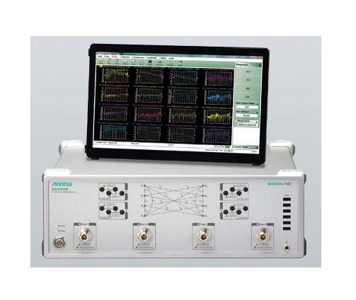
The Anritsu MS46524B is a 4-port vector network analyzer from the ShockLine Performance family, designed for measuring the S-parameters of passive multiport and differential devices. Available in three frequency configurations covering 50 kHz to 8.5 GHz, 20 GHz, or 43.5 GHz, it provides 16 single-ended and 16 mixed-mode S-parameter measurements in a 3U rack-mountable chassis. The instrument is operated through a graphical user interface displayed on a user-supplied touchscreen monitor, keyboard, and mouse, and supports SCPI command programming for automated test integration.
A vector network analyzer characterizes how RF signals transmit through and reflect off components and networks across a defined frequency range. By generating a known stimulus signal and measuring both magnitude and phase of the response at each port, the VNA produces the complete S-parameter set that describes the device's RF behavior. This makes the VNA the primary instrument for designing and verifying filters, amplifiers, antennas, cables, connectors, and complex multi-port modules where impedance matching and frequency response must be precisely understood.
ValueTronics has supported engineers and labs working with vector network analyzers since 1992, and the MS46524B is exactly the kind of instrument our team is built to support. Every unit we sell — new through our authorized distribution relationships, or pre-owned after passing our verification process — is handled out of our 20,000 square foot facility at 1675 Cambridge Drive in Elgin, Illinois. We keep the test ports protected, the calibration data accessible, and the documentation matched to the instrument so that when a 4-port VNA leaves our warehouse, it arrives ready for the bench it was purchased for.
Anritsu Corporation, headquartered in Atsugi, Japan, has roots in test and measurement extending back to 1895. The company's modern RF and microwave VNA portfolio was significantly shaped by its 1993 acquisition of Wiltron Company, a respected US RF instrument maker whose network analyzer technology and North American commercial presence became part of Anritsu. The ShockLine VNA family represents Anritsu's continued development of high-performance, compact-footprint vector network analyzers for both production and R&D environments.
The MS46524B is a single 4-port ShockLine Performance VNA platform that is configured through a mandatory frequency option at order time. The base instrument hardware, software, calibration methods, and remote control architecture are identical across the family — the three published configurations differ in frequency coverage, the front-panel test port connector type, and the test-port damage and source-power profiles tied to those connectors.
The three frequency options span common RF and microwave application bands: the 8.5 GHz option (Option 010) targets cellular, WiFi, and general sub-10 GHz component characterization with Type N(f) ports; the 20 GHz option (Option 020) extends into K-band applications using K(m) ruggedized ports; and the 43.5 GHz option (Option 043) reaches into Ka-band and millimeter-wave-adjacent work using Extended-K(m) ruggedized ports that also accept K, 3.5 mm, and SMA mating connectors.
Each pre-owned MS46524B configuration below is listed as its own product page with condition-matched pricing and the specific frequency option built in. The base model number is shared across the family, so confirm the frequency option suffix (-010, -020, or -043) matches the application frequency range before ordering.
Within the family, the higher-frequency configurations carry tighter output-power and dynamic-range characteristics at their upper bands as published in the datasheet: maximum source power decreases from +15 dBm in the mid-band to approximately +6 dBm above 8.5 GHz and approximately +2 dBm above 40 GHz, and system dynamic range follows a similar tapered profile by frequency segment.
The most important differentiator between the three configurations is the frequency option and its associated test-port connector. The MS46524B-010 (N-type ports, 8.5 GHz) is the entry point and the only configuration that supports the Bias Tee option (-061). The MS46524B-020 (K-type, 20 GHz) and MS46524B-043 (Extended-K, 43.5 GHz) extend coverage upward but use ruggedized K-family connectors that are mechanically and electrically distinct from N-type.
Beyond frequency coverage, the optional software capabilities — Time Domain (Option 002), Advanced Time Domain (Option 022), and Universal Fixture Extraction (Option 024) — apply equally across all three frequency configurations. Refer to the comparison table that follows for the published frequency, connector type, and source power values for each configuration as a side-by-side reference.
| Model | Frequency Range | Test Port Connector | Number of Ports |
|---|---|---|---|
| MS46524B | — | — | 4 |
| MS46524B-010 | 50 kHz to 8.5 GHz | N(f) | 4 |
| MS46524B-020 | 50 kHz to 20 GHz | K(m) Ruggedized | 4 |
| MS46524B-043 | 50 kHz to 43.5 GHz | Extended-K(m) Ruggedized | 4 |
Additional differences in specifications beyond the few shown above are not listed here — see each model's full specifications below.
| Parameter | Specification |
|---|---|
| Receiver Compression Levels (Characteristic) | |
| 50 kHz to 300 kHz | +10 dBm |
| > 300 kHz to 8 GHz (8.5 GHz for Option 10) | +15 dBm |
| > 8 GHz to 43.5 GHz | +10 dBm |
| High Level Noise (100 Hz IF BW, default power, RMS) | |
| 50 kHz to 300 kHz | Magnitude: 0.02 dB (0.01 typ); Phase: 0.15° (0.08 typ) |
| > 300 kHz to 1 GHz | Magnitude: 0.004 dB (0.003 typ); Phase: 0.04° (0.02 typ) |
| > 1 GHz to 25 GHz | Magnitude: 0.004 dB (0.002 typ); Phase: 0.05° (0.02 typ) |
| > 25 GHz to 43.5 GHz | Magnitude: 0.004 dB (0.002 typ); Phase: 0.05° (0.04 typ) |
| Output Default Power | |
| Default Power | 0 dBm |
| Power Accuracy | |
| At 0 dBm, 50 kHz to 8.5 GHz | ± 1.5 dB (± 0.5 typ) |
| At 0 dBm, > 8.5 GHz to 25 GHz | ± 2.0 dB (± 0.5 typ) |
| At 0 dBm, > 25 GHz to 40 GHz | ± 2.5 dB (± 0.5 typ) |
| At 0 dBm, > 40 GHz to 43.5 GHz | ± 3.0 dB (± 1.0 typ) |
| At -30 dBm (typical) | ± 3.0 dB across all bands |
| Power Setting Resolution | |
| 50 kHz to 43.5 GHz | 0.01 dB |
| Measurement Stability (Ratio, ports shorted, typical) | |
| 50 kHz to 8.5 GHz | 0.02 dB/°C magnitude; 0.5°/°C phase |
| > 8.5 GHz to 40 GHz | 0.01 dB/°C magnitude; 1.0°/°C phase |
| > 40 GHz to 43.5 GHz | 0.02 dB/°C magnitude; 1.5°/°C phase |
| Frequency Resolution, Accuracy, and Stability | |
| Resolution | 1 Hz |
| Accuracy (at time of calibration) | ± 0.1 ppm |
| Stability vs. Temperature | ± 0.1 ppm / 10 °C to 50 °C |
| Stability (typical) | ± 0.02 ppm/24 hours; ± 0.2 ppm/1 month; ± 1.0 ppm/1 year; ± 2.0 ppm/3 years |
| Source Harmonics and Non-Harmonics (typical, at 0 dBm) | |
| 50 kHz to 8 GHz (8.5 GHz Opt 10) | Harmonics: < -30 dBc; Spurious: < -30 dBc; Phase Noise @10 kHz: < -60 dBc/Hz |
| > 8 GHz to 15 GHz | Harmonics: < -12 dBc; Spurious: < -30 dBc; Phase Noise: < -60 dBc/Hz |
| > 15 GHz to 22 GHz | Harmonics: < -15 dBc; Spurious: < -30 dBc; Phase Noise: < -60 dBc/Hz |
| > 22 GHz to 43.5 GHz | Harmonics: < -20 dBc; Spurious: < -30 dBc; Phase Noise: < -60 dBc/Hz |
| Uncorrected (Raw) Port Characteristics (typical) | |
| 50 kHz to 4 GHz | Directivity > 21 dB; Port Match > 17 dB |
| > 4 GHz to 43.5 GHz | Directivity > 15 dB; Port Match > 15 dB |
| Measurement Parameters | |
| 4-Port Measurements | 16 single-ended S-parameters; 16 mixed-mode S-parameters (DD, CC, DC, CD) |
| Domains | Frequency, Time (Distance) Domain (Option 2), Power |
| Sweeps | |
| Sweep Configurations | Standard or Simultaneous (MS46524B-010 option only) |
| Frequency Sweep Types | Linear, Log, CW, or Segmented |
| Power Sweep Types | Linear |
| Channels, Display, and Traces | |
| Channels and Traces | 16 channels, each with up to 16 traces |
| Maximum Data Points | 2 to 20,001 points |
| Trace Memory | Up to 20 trace memories per channel |
| Markers | 12 markers + 1 reference marker per trace |
| IF Bandwidth | |
| Available Bandwidths | 10, 20, 30, 50, 70, 100, 200, 300, 500, 700 Hz; 1, 2, 3, 5, 7, 10, 20, 30, 50, 70, 100, 200, 300, 500 kHz |
| Averaging | |
| Point-by-Point | Maximum 4096 averages |
| Sweep-by-Sweep | Maximum 4096 averages |
| Calibration Methods | |
| Methods Supported | SOLT, SOLR, SSLT, SSST, LRL/LRM, Source Cal, Receiver Cal, SmartCal, AutoCal |
| Front Panel | |
| USB Ports (Front) | Six Type A USB 2.0 ports |
| Chassis Grounding Port | Banana(f) |
| Rear Panel | |
| AC Power Input | 350 VA maximum, 90 to 264 VAC, 47 to 63 Hz (power factor controlled) |
| USB Ports (Rear) | Four Type A USB 3.0 ports |
| LAN Port | Gigabit Ethernet |
| Media | HDMI and Display Port video output, touchscreen compatible; 3.5 mm stereo audio |
| 10 MHz In | BNC(f); +0 dBm typical; 50 Ω nominal |
| 10 MHz Out | BNC(f); +8 dBm typical; 50 Ω nominal |
| External Trigger Input | BNC(f); 0 to 3.3 V (5 V tolerant); >100 kΩ impedance; 50 ns min pulse width; 6 µs typ trigger delay |
| External Trigger Output | BNC(f); 0 to 3.3 V (HCMOS); 24 mA max drive; 1 µs typ pulse width |
| Bias Inputs (Option 10 only) | BNC(f), one per port; 50 VDC max, 0.5 A max |
Please review the Manufacturer's Data Sheet to verify published specifications. Feedback on this webpage is always welcome — please reach out to your Test Architect at any time for questions or concerns. Thank you, we truly appreciate you being our customer.
Model No
Anritsu
Condition
Used
Manufacturer
Anritsu
Frequency
43.5 GHz

30+ Years in Business
Secure Payments
Sell Test Equipments
Knowledgeable Staff
On-site Lab
30+ Years in Business
Secure Payments
Sell Test Equipments
Knowledgeable Staff
On-site Lab
Request A Quote
 Chat Live
 Contact Us
 sales@valuetronics.com