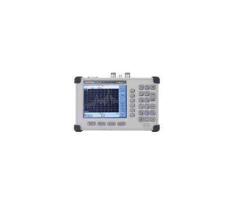
The Anritsu Site Master S311D/S312D is a handheld, field-oriented cable and antenna analyzer built on Anritsu's Site Master series. The S311D provides a 25 MHz to 1600 MHz cable and antenna analyzer, while the S312D combines that same high-performance cable and antenna analyzer with a fully functional spectrum analyzer covering 100 kHz to 1600 MHz. Both models are designed for accurate, portable, rugged, and easy-to-use field measurement, with a menu-driven interface that requires little or no training time.
The Site Master is positioned for Land Mobile Radio (LMR) and Public Safety system work, including testing the RF performance of P25 and TETRA radios across the VHF/UHF, 700 MHz, and 800 MHz bands. With frequency coverage reaching down to 2 MHz (via the low-frequency option), it also supports defense applications in the HF band, and the S31xD series is suited to broadcast and cellular applications as well. The cable and antenna analyzer sweeps cables and antennas at the frequency of operation using Return Loss and VSWR measurements, while Distance-To-Fault pinpoints poor connections, contamination, damaged cables, water penetration, and bad antennas.
ValueTronics stocks and holds its own inventory in a 20,000 sq ft secure warehouse at 1675 Cambridge Drive in Elgin, Illinois, so the instruments we list are equipment we keep on hand rather than source on demand. Every used unit is inspected and functionally verified in-house before it ships, while new units ship factory-sealed exactly as received from the manufacturer. This combination lets our team match the right Site Master configuration to your application and ship it with confidence in its condition.
The Site Master S311D/S312D family pairs Anritsu's rugged field-instrument design with two model tiers built around the same 1600 MHz cable and antenna analyzer. The S311D is a dedicated cable and antenna analyzer, while the S312D combines that analyzer with a fully functional spectrum analyzer and a wider catalog of measurement options.
Both models share the same handheld chassis, TFT color display, six-language interface, RS-232 connectivity, and Frequency Domain Reflectometry measurement engine, so the choice between them comes down to which measurement functions and options a given field application requires.
Each pre-owned model below is its own dedicated product page with condition-matched pricing. Select the model that fits your application, then choose the listing that matches the condition and configuration you need.
The S312D is the dual-function member of the family: it adds the 100 kHz to 1600 MHz spectrum analyzer and the ≤–135 dBm noise floor that Anritsu calls out for tracking low-level interference on LMR and SMR systems, and it supports options such as the Interference Analyzer, Transmission Measurement, Channel Scanner, CW Signal Generator, Power Meter, and Bias Tee that are not offered on the S311D.
The primary difference between the models is the spectrum analyzer: the S312D includes a 100 kHz to 1.6 GHz spectrum analyzer (tunable to 9 kHz) with a +20 dBm to –135 dBm measurement range, while the S311D is a cable and antenna analyzer only. The two models also differ in setup storage, with the S311D supporting 10 to 20 saved setups and the S312D supporting 15 to 40.
Option availability follows the same split. The S311D options are the 2 MHz Frequency Extension, Power Monitor, High Accuracy Power Meter, and GPS Receiver; the S312D adds the Bias Tee, Transmission Measurement, Interference Analyzer, Channel Scanner, CW Signal Generator, and Power Meter options. See the comparison table for the per-model frequency ranges, functions, and option codes.
| Model | CAA Frequency Range | Spectrum Analyzer | Noise Floor (DANL) |
|---|---|---|---|
| S312D | 25 MHz to 1.6 GHz | 100 kHz to 1.6 GHz | ≤–135 dBm |
| S311D | 25 MHz to 1.6 GHz | — | — |
Additional differences in specifications beyond the few shown above are not listed here — see each model's full specifications below.
| Specification | Value |
|---|---|
| Cable and Antenna Analyzer | |
| Frequency Range | 25 MHz to 1.6 GHz |
| Frequency Accuracy | ≤±75 ppm at +25 °C |
| Frequency Resolution | 100 kHz |
| Output Power | <0 dBm (–10 dBm nominal) |
| Immunity to Interfering Signals | On-channel: +17 dBm; On-frequency: –5 dBm |
| Measurement Speed | ≤3.5 msec / data point (CW ON) |
| Number of Data Points | 130, 259, 517 |
| Return Loss | Range: 0.00 to 60.00 dB; Resolution: 0.01 dB |
| VSWR | Range: 1.00 to 65.00; Resolution: 0.01 |
| Cable Loss | Range: 0.00 to 30.00 dB; Resolution: 0.01 dB |
| Measurement Accuracy | >42 dB directivity after calibration |
| Distance-to-Fault Vertical Range | Return Loss: 0.00 to 60.00 dB; VSWR 1.00 to 65.00 |
| Distance-to-Fault Horizontal Range | 0 to (# of data pts –1) x Resolution to a maximum of 1497 m (4909 ft), # of data pts = 130, 259 or 517 |
| Horizontal Resolution (Rectangular Windowing) | Resolution (meter) = (1.5 x 10^8) x (Vp)/∆F, where Vp is the cable's relative propagation velocity and ∆F is the stop frequency minus the start frequency (in Hz) |
| 2 MHz Frequency Extension (Option 2) | |
| Frequency Range | 2 MHz to 1600 MHz (all other specs remain the same as standard S31xD) |
| Spectrum Analyzer | |
| Frequency Range | 100 kHz to 1.6 GHz (tunable to 9 kHz) |
| Frequency Reference (Internal Timebase) Aging | ±1 ppm/yr |
| Frequency Reference Accuracy | ±2 ppm |
| Frequency Span | 10 Hz to 1.599 GHz in 1, 2, and 5 step selections in auto mode, plus zero span |
| Sweep Time | ≤1.1 sec full span; ≤50 µsec to 20 sec selectable in zero span |
| Resolution Bandwidth (–3 dB) | 100 Hz to 1 MHz in 1-3 sequence ±5% Accuracy |
| Video Bandwidth (–3 dB) | 3 Hz to 1 MHz in 1-3 sequence ±5% Accuracy typical |
| SSB Phase Noise (1 GHz) at 30 kHz Offset | ≤–75 dBc/Hz |
| Spurious Responses Input Related | ≤–45 dBc |
| Spurious Residual Responses | ≤–90 dBm, ≥10 MHz; ≤–80 dBm, <10 MHz (10 kHz RBW, pre-amp on) |
| Total Level Accuracy | ±1 dB typical (±1.5 dBm max), ≥10 MHz to 1.6 GHz; ±2 dB typical, <10 MHz for input signal levels ≥–60 dBm, excludes input VSWR mismatch |
| Measurement Range | +20 dBm to –135 dBm |
| Input Attenuator Range | 0 to 51 dB, selected manually or automatically coupled to the reference level. Resolution in 1 dB steps |
| Displayed Average Noise Level | ≤–135 dBm, ≥10 MHz (preamp on); ≤–115 dBm, <10 MHz (preamp on) for input terminated, 0 dB attenuation, RMS detection, 100 Hz RBW |
| Dynamic Range | >65 dB, typical |
| Display Range | 1 to 15 dB/division, in 1 dB steps, 10 divisions displayed |
| Scale Units | dBm, dBV, dBmV, dBmV, V, W |
| RF Input VSWR | (with ≥20 dB atten.), 1.5:1 typical, (10 MHz to 1.6 GHz) |
| Power Monitor (Option 5) | |
| Display Range | –80 to +80 dBm (10 pW to 100 kW) |
| Measurement Range | –50 to +16 dBm (10 nW to 40 mW) |
| Resolution | 0.1 dB, 0.1 xW |
| Accuracy | ±1 dB |
| Bias Tee (Option 10A) | |
| Voltage | +12 V to +24 V (variable in 1 V steps) |
| Power | 6 W steady state |
| Current | 6 W/Voltage (V) |
| High Accuracy Power Meter PSN50 (Option 19) | |
| Sensor Measurement Range | –30 to +20 dBm |
| Sensor Frequency Range | 50 MHz to 6 GHz |
| Input Connector | Type N, male, 50 Ω |
| Max Input without Damage | +33 dBm, ±25 VDC |
| Input Return Loss | 50 MHz to 2 GHz: ≥26 dB; 2 GHz to 6 GHz: ≥20 dB |
| Total RSS Measurement Uncertainty (0 to 50 °C) | ±0.16 dB |
| Noise | 20 nW max |
| Zero Set | 20 nW |
| Zero Drift | 10 nW max (after 30 minute warm-up) |
| Sensor Linearity | ±0.13 dB max |
| Instrumentation Accuracy | 0.00 dB |
| Sensor Cal Factor Uncertainty | ±0.06 dB |
| Temperature Compression | ±0.06 dB max |
| Continuous Digital Modulation Uncertainty | +0.06 dB (+17 to +20 dBm) |
| Measurement Resolution | 0.01 dB |
| Offset Range (System) | ±60 dB |
| Supply Voltage | 8 to 18 Vdc |
| Supply Current | <100 mA |
| Transmission Measurement (Option 21) | |
| Frequency Range | 25 MHz to 1.6 GHz |
| Frequency Resolution | 10 Hz |
| Output Power Level | –10 dBm typical |
| Dynamic Range | 80 dB |
| Output Impedance | 50 Ω |
| Channel Scanner (Option 27) | |
| Frequency Range | 100 kHz to 1.6 GHz |
| Frequency Accuracy | ±10 Hz + Time base error, 99% confidence level |
| Measurement Range | +20 dBm to –100 dBm |
| Offset Range | 0 to +60 dB |
Important: Maximum input without damage (RF In, Type N female, 50 Ω): +43 dBm peak, ±50 VDC.
Important: High Accuracy Power Meter (Option 19) requires the Anritsu PSN50 sensor, which is not included with the option (PSN50 sensor not included).
Important: Power Monitor (Option 5) requires an external detector, which is not included.
Important: Interference Analyzer (Option 25) requires a directional antenna, which is not included.
Important: CW Signal Generator (Option 28) requires the CW Signal Generator Kit (part number 61534).
Important: The standard cable and antenna analyzer spans 25 MHz to 1600 MHz; lower-frequency coverage down to 2 MHz requires the 2 MHz Frequency Extension (Option 2).
This pre-owned unit is inspected and functionally verified in-house before it ships and is backed by our pre-owned warranty. To confirm its exact condition, firmware revision, installed options, or included accessories for your application before ordering, contact our Test Architects.
ValueTronics supplies both new and used test and measurement equipment. New units ship factory-sealed, exactly as received from the manufacturer; every used unit is inspected and functionally verified in-house at our 20,000 sq ft secure facility in Elgin, Illinois before it ships. Our Test Architects can help you select the condition, calibration, and configuration that fit your application.
Please review the Manufacturer's Data Sheet to verify published specifications. Feedback on this webpage is always welcome — please reach out to your Test Architect at any time for questions or concerns. Thank you, we truly appreciate you being our customer.
Model No
Anritsu
Condition
Pre-Owned
Manufacturer
Anritsu
Cabant_ana_freq
25 MHz to 1.6 GHz

30+ Years in Business
Secure Payments
Sell Test Equipments
Knowledgeable Staff
On-site Lab
30+ Years in Business
Secure Payments
Sell Test Equipments
Knowledgeable Staff
On-site Lab
Request A Quote
 Chat Live
 Contact Us
 sales@valuetronics.com