The Agilent 81134A is a 2-channel 3.35 GHz pulse pattern generator designed for digital device characterization tasks where leading-edge signal integrity and timing performance are required. It provides programmable pulse periods from 15 MHz (66.6 ns) down to 3.35 GHz (298.5 ps) on all channels, with differential outputs and full control over signal parameters to enable typical and worst-case device tests. A companion 1-channel model, the 81133A, shares the same core architecture.
The instrument is used for simulating the pulse and pattern conditions that a digital device will encounter in its final application. Datasheet-listed use cases include signal integrity measurements, generation of real-world-like signals by adding jitter to clock or data signals, distorting signals for eye diagram measurements, PLL frequency sweep, and microprocessor clock sweep applications where dropouts would otherwise prevent reliable measurement.
Agilent Technologies was spun out of Hewlett-Packard's test and measurement business in 1999. In 2014, Agilent's electronic measurement business became Keysight Technologies, which carries the direct product lineage and continued support for Agilent-era pulse and pattern generators including the 81133A and 81134A.
The 81133A and 81134A share a common 3.35 GHz pulse/pattern generation architecture, the same timing and jitter performance, the same 12 Mbit per-channel pattern memory, and the same Delay Control Input for jitter injection. The two models differ only in channel count and the corresponding front-panel I/O configuration.
Both instruments support NRZ, RZ, and R1 data formats, PRBS sequences from 2^5−1 to 2^31−1, programmable amplitude from 50 mV to 2.00 V, and SCPI control over GPIB, LAN, and USB 2.0. The same store/recall behavior, the same direct-mode dropout-free frequency change capability, and the same Variable Crossover and jitter emulation features apply across the family.
Each pre-owned model below is listed on its own dedicated product page with condition-matched pricing and availability. The two models are not interchangeable on the bench: choose the 81133A when a single differential channel meets the application requirement, and choose the 81134A when two independent differential channels with separate Delay Control Inputs are required.
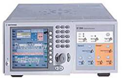
The 81134A is the 2-channel configuration. Its front panel provides four output connectors for the two differential channels, a trigger output, a clock input, a start input, and two Delay Control Inputs—one for each output channel. This allows independent jitter injection per channel and is the configuration shown in the datasheet's Jitter Emulation Test Setup.
The 81133A provides one differential channel with two output connectors and one Delay Control Input. The 81134A provides two differential channels with four output connectors and two Delay Control Inputs, one per channel. Trigger output, clock input, and start input are present on both models.
Pulse, data, and PRBS modes are independently configurable per channel on the 81134A, which makes it the appropriate choice for differential receiver test setups requiring two phase-correlated or independently-jittered stimulus signals. The comparison table that follows lists channel count and the resulting front-panel I/O differences side by side.
| Model | Channels | Frequency Range | Pattern Memory |
|---|---|---|---|
| 81133A | 1 | 15 MHz to 3.35 GHz | 12 MBit per channel |
| 81134A | 2 | 15 MHz to 3.35 GHz | 12 MBit per channel |
Additional differences in specifications beyond the few shown above are not listed here — see each model's full specifications below.
| Internal Clock Generation | |
|---|---|
| Period Range | 298.5 ps - 66.6 ns |
| Period Resolution | 6 digits, 0.001 ps best case |
| Frequency Range | 15 MHz - 3.35 GHz |
| Frequency Resolution | 1 Hz |
| Accuracy | 50 ppm |
| Jitter | |
| Random Jitter (Clock Mode) | <4 ps RMS (1.5 ps typical) |
| Total Jitter (Data Mode) | <5 ps RMS (2 ps typical) (<30 ps pp (12 ps typical)) |
| Channel Output Timing | |
| Number of Channels | 1 (81133A), 2 (81134A) |
| Transition Times (10% to 90%) | < 90 ps |
| Transition Times (20% to 80%) | < 60 ps |
| Delay Variation | -5 ns to 230 ns |
| Delay Resolution | 1 ps |
| Delay Accuracy | ± 20 ps |
| Phase | -6000° to +279000° |
| Phase Resolution | 0.01°, or 1 ps |
| Skew Between Differential Outputs | < 20 ps nominal |
| Maximum Skew Range | ± 10 ns |
| Width Range | 100 ps to (period - 100 ps) |
| Width Resolution | 1 ps |
| Width Accuracy | ± 40 ps |
| Duty Cycle Range | 0.15% - 99.85% |
| Duty Cycle Resolution | 0.002%, or 1 ps |
| Divide By | 1, 2, 4, 8, 16, 32, 64, 128 |
| Transition Times (Pulse Performance) | |
| Fast | 60 ps to 70 ps |
| Normal | 70 ps to 80 ps |
| Smooth | 80 ps to 120 ps |
| Channel Output Levels | |
| Amplitude | 50 mV to 2.00 V |
| Level Window | -2.00 V to +3.00 V |
| Level Resolution | 10 mV |
| Level Accuracy | 2% of setting ± 20 mV |
| Amplitude Accuracy | 2% ± 20 mV |
| Settling Time | 1 ns |
| Overshoot, Ringing | <10% ± 10 mV differential outputs |
| Variable Crossover | 30% to 70% typical |
| Maximum External Termination Voltage | -2.00 V to +3.00 V |
| Short Circuit Current | 80 mA <= Isc <= 120 mA nominal |
| Limit | High and low levels into 50 Ohm can be limited |
| Normal/Complement | Selectable |
| Disable | Yes (relay) |
| Trigger Output | |
| Amplitude | 50 mV to 2.00 V |
| Level Window | -2.00 V to +3.00 V |
| Resolution | 10 mV |
| Format | Fixed Duty Cycle, 50% nominal |
| Maximum External Voltage | -2.00 V to +3.00 V |
| Transition Times (20% to 80% of amplitude) | < 100 ps (< 60 ps typical) |
| Minimum Output Frequency | 15 MHz / Divider Factor |
| Mode | Clock divided by 1, 2, 3, ... 2^31-1 or trigger on bit 0 of data |
| Disable | Yes (relay) |
| Clock Input | |
| Interface | ac-coupled with optional dc termination |
| Impedance | 50 Ohm |
| Termination Voltage | -2.0 V to +3.0 V |
| Minimum Swing | 300 mV, tr < 3 ns, 50% duty cycle, sine: 0 dBm |
| Maximum Amplitude | 3 Vpp, ± 5 Vdc |
| Frequency Measurement | Yes |
| Period Range | 299 ps to 66.6 ns |
| Period Resolution | 6 digits, 0.001 ps best case |
| Frequency Range | 15 MHz to 3.35 GHz |
| Measurement Resolution | 100 kHz |
| Measurement Accuracy | 50 ppm |
| Start Input | |
| Modes | Start |
| Impedance | 50 Ohm nominal |
| Termination Voltage | 2.0 V to 3.0 V |
| Transitions | < 1 ns |
| Threshold | -1.8 V to +4 V |
| Max. Level Window | -2 V to +5 V |
| Propagation Delay | |
| Clock Input to Trigger Output | 8.4 ns nominal, fixed |
| Trigger Output to Channel Output | 32 ns nominal variable |
| Data Generation | |
| Memory Depth | 12 MBit per channel, 8 kBit accessible from front panel |
| Data Format | RZ / NRZ / R1 |
| Granularity of Data Pattern Length | 32 Bit up to 8 kBit; 128 Bit from 8 kBit to 12 MBit |
| Interface | dc-coupled |
| Impedance | 50 Ohm nominal |
Please review the Manufacturer's Data Sheet to verify published specifications. Feedback on this webpage is always welcome — please reach out to your Test Architect at any time for questions or concerns. Thank you, we truly appreciate you being our customer.
Model No
Agilent
Condition
Used
Manufacturer
Agilent

30+ Years in Business
Secure Payments
Sell Test Equipments
Knowledgeable Staff
On-site Lab
30+ Years in Business
Secure Payments
Sell Test Equipments
Knowledgeable Staff
On-site Lab
Request A Quote
 Chat Live
 Contact Us
 sales@valuetronics.com