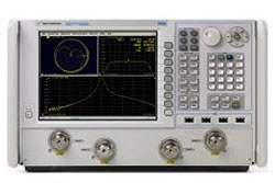
The Agilent N5224A and N5225A are PNA network analyzers offered in both 2-port and 4-port configurations. The N5224A covers 10 MHz to 43.5 GHz and the N5225A covers 10 MHz to 50 GHz, providing vector measurement of reflection and transmission characteristics across the microwave range. Both models share a common platform and selectable option set, differing principally in their upper frequency limit and the configuration chosen at order time.
A network analyzer characterizes how RF and microwave components respond to applied stimulus signals, measuring the scattering parameters that describe reflection and transmission behavior. These analyzers support full 2-port calibrated S-parameter measurements and group delay measurements. Internal receiver gates enable point-in-pulse and pulse-profile measurements, while external IF inputs allow the use of external IF signals from remote mixers by bypassing the analyzer's first converters, and an external test set driver is provided for driving remote mixers.
ValueTronics stocks and holds its own inventory in a 20,000 square-foot secure warehouse at 1675 Cambridge Drive in Elgin, Illinois. Every pre-owned unit is inspected and functionally verified in-house before it ships, while new units ship factory-sealed exactly as received from the manufacturer. Holding inventory directly lets our team match the right instrument and configuration to your application and move it quickly when you order.
Agilent Technologies was formed in 1999 as a spin-off of the test and measurement business of Hewlett-Packard. In 2014, Agilent's electronic measurement division was established as an independent company, Keysight Technologies, which carried forward the network analyzer product lines.
The PNA family on this page comprises the N5224A and N5225A, two- and four-port vector network analyzers that share a common platform, display, and connectivity. They are distinguished by frequency coverage and by the option configuration selected at order time, allowing a buyer to match upper frequency limit and port count to the measurement task.
Across both models, the option structure follows a consistent pattern: a base test set, then progressive additions of front-panel jumpers and an R1 receiver switch, source and receiver attenuators for extended power range, and bias-tees. The comparison table below lays out how frequency range, port count, and option content differ across the configurations.
Each model in the family below links to its own dedicated product page with pre-owned-matched pricing. Select the model and frequency coverage that fit your application, then choose the configuration and condition that meet your budget and lead-time requirements.
The primary difference between the two models is upper frequency limit: the N5224A covers 10 MHz to 43.5 GHz, while the N5225A extends to 50 GHz and carries additional specified performance in the 43.5 GHz to 50 GHz band. Both are available as 2-port or 4-port instruments with a standard test set.
Within each model, the option suffix defines the test set content. Options 201/401 add front-panel jumpers and an R1 receiver switch; Options 217/417 further add source and receiver attenuators for extended power range; and Options 219/419 add bias-tees on top of the extended-power-range hardware. These differences affect available power range, direct receiver access, and damage input level, as detailed in the comparison table that follows.
| Model | Frequency Range | Max Output Power | Test Port Connector |
|---|---|---|---|
| N5225A | 10 MHz to 50 GHz | 30 dBm | 2.4 mm (male), 50 Ω |
| N5224A | 10 MHz to 43.5 GHz | 30 dBm | 2.4 mm (male), 50 Ω |
Additional differences in specifications beyond the few shown above are not listed here — see each model's full specifications below.
| Specification | Value |
|---|---|
| Frequency Information, All Options (Table 6) | |
| Frequency Range | 10 MHz to 50 GHz |
| Frequency Resolution | 1 Hz |
| Frequency Accuracy | +/- 1 ppm |
| Frequency Stability (typical) | +/-0.05 ppm, -10 ° to 70 °C; +/-0.1 ppm/yr maximum |
| System Dynamic Range (dB), Option 200/400 (Table 1b, Specification) | |
| 10 MHz to 50 MHz | 82 |
| 50 MHz to 100 MHz | 98 |
| 100 MHz to 250 MHz | 108 |
| 250 MHz to 500 MHz | 115 |
| 500 MHz to 1 GHz | 119 |
| 1 GHz to 10 GHz | 127 |
| 10 GHz to 26.5 GHz | 127 |
| 26.5 GHz to 35 GHz | 123 |
| 35 GHz to 40 GHz | 118 |
| 40 GHz to 43.5 GHz | 118 |
| 43.5 GHz to 47 GHz | 115 |
| 47 GHz to 50 GHz | 107 |
| Maximum Leveled Power (dBm), Option 200/400 (Table 7a, Specification) | |
| 10 MHz to 50 MHz | 12 |
| 50 MHz to 16 GHz | 13 |
| 16 GHz to 26.5 GHz | 13 |
| 26.5 GHz to 30 GHz | 13 |
| 30 GHz to 32 GHz | 13 |
| 32 GHz to 35 GHz | 13 |
| 35 GHz to 43.5 GHz | 10 |
| 43.5 GHz to 47 GHz | 6 |
| 47 GHz to 50 GHz | -2 |
| Test Port Noise Floor (dBm) @ 10 Hz IFBW, N5225A (Table 16, Specification) | |
| 10 MHz to 50 MHz | -70 |
| 50 MHz to 100 MHz | -85 |
| 100 MHz to 250 MHz | -95 |
| 250 MHz to 500 MHz | -102 |
| 500 MHz to 1 GHz | -106 |
| 1 GHz to 10 GHz | -114 |
| 10 GHz to 26.5 GHz | -114 |
| 26.5 GHz to 35 GHz | -110 |
| 35 GHz to 40 GHz | -108 |
| 40 GHz to 43.5 GHz | -108 |
| 43.5 GHz to 50 GHz | -109 |
| Power Level Accuracy (dB), All Options (Table 8, Specification) | |
| 10 MHz to 1 GHz | +/- 1.0 |
| 1 GHz to 3.2 GHz | +/- 1.2 |
| 3.2 GHz to 13.5 GHz | +/- 1.5 |
| 13.5 GHz to 20 GHz | +/- 1.5 |
| 20 GHz to 26.5 GHz | +/- 1.8 |
| 26.5 GHz to 43.5 GHz | +/- 2.2 |
| 43.5 GHz to 50 GHz | +/- 3.2 |
| Nominal (Preset) Power (dBm), N5225A (Table 11) | |
| Option 200, 201, 400, 401 | -5 |
| Option 217, 219, 417, 419 | -15 |
| Power Resolution and Max/Min Settable Power (Table 12) | |
| Power Resolution | 0.01 dB |
| Maximum Settable Power (typical) | 30 dBm |
| Minimum Settable Power, Option 200/201/400/401 (typical) | -30 dBm |
| Minimum Settable Power, Option 217/219/417/419 (typical) | -90 dBm |
| 2nd and 3rd Harmonics at Max Specified Power (dBc), N5225A (Table 13, Typical) | |
| 20 MHz to 4 GHz | -15 |
| 4 GHz to 6 GHz | -18 |
| 6 GHz to 24 GHz | -19 |
| 24 GHz to 27 GHz | -21 |
| 27 GHz to 40.5 GHz | -29 |
| 40.5 GHz to 43.5 GHz | -60 |
| 43.5 GHz to 50 GHz | -60 |
| Phase Noise (dBc/Hz), All Options (Table 15, Typical) [1 kHz / 10 kHz / 100 kHz / 1 MHz offset] | |
| 10 MHz to 50 MHz | -100 / -95 / -95 / -120 |
| 50 MHz to 1 GHz | -107 / -117 / -112 / -127 |
| 1 GHz to 2 GHz | -101 / -111 / -106 / -121 |
| 2 GHz to 4 GHz | -95 / -105 / -100 / -115 |
| 4 GHz to 8 GHz | -89 / -99 / -94 / -109 |
| 8 GHz to 16 GHz | -83 / -93 / -88 / -103 |
| 16 GHz to 32 GHz | -77 / -87 / -82 / -97 |
| 32 GHz to 50 GHz | -71 / -81 / -76 / -91 |
| Damage Input Level, All Ports (Table 23) | |
| RF, DC — Option 200, 201, 219, 400, 401, 419 | 27 dBm, 40 V |
| RF, DC — Option 217, 417 | 27 dBm, 7 V |
Important: Damage input level, all ports: +27 dBm RF; +40 VDC (Options 200, 201, 219, 400, 401, 419) or +7 VDC (Options 217, 417).
Important: All specifications and characteristics apply over a 25 °C ±5 °C range (unless otherwise stated) and 90 minutes after the instrument has been turned on.
Important: With a thru connection between the test ports of an Option 217 or 417 configuration, 7 VDC input to the CPLR THRU ports damages the source attenuator on the connected port (Table 39 footnote).
Important: Test Port Noise Floor and Direct Receiver Access Input Noise Floor may typically be degraded at particular frequencies below 500 MHz due to spurious receiver residuals.
Recommended pairing: the Agilent 85056A calibration kit or the N4693A 2-port electronic calibration module, used with the 85133F flexible test port cable set, for the full 2-port calibrated measurements these specifications are based on.
This pre-owned unit is inspected and functionally verified in-house before it ships and is backed by our pre-owned warranty. To confirm its exact condition, firmware revision, installed options, or included accessories for your application before ordering, contact our Test Architects.
ValueTronics supplies both new and used test and measurement equipment. New units ship factory-sealed, exactly as received from the manufacturer; every used unit is inspected and functionally verified in-house at our 20,000 sq ft secure facility in Elgin, Illinois before it ships. Our Test Architects can help you select the condition, calibration, and configuration that fit your application.
Please review the Manufacturer's Data Sheet to verify published specifications. Feedback on this webpage is always welcome — please reach out to your Test Architect at any time for questions or concerns. Thank you, we truly appreciate you being our customer.
Model No
Agilent
Condition
Pre-Owned
Manufacturer
Agilent Technologies
Net_ana_freq
10 MHz to 50 GHz
7
Automatic Fixture Removal
8
Pulsed-RF Measurements
10
Time-domain measurements
15
Dynamic Uncertainty for S-Parameter Measurements
20
Add IF inputs
21
Add pulse modulator to internal first source
22
Add pulse modulator to internal second source
25
Internal pulse generators , Add 4
28
Noise figure measurements using standard receivers
29
Fully-corrected noise-figure measurements to 13.5 GHz
80
Frequency offset measurements
82
Scalar calibrated converter measurements
83
Vector and scalar calibrated converter measurements
84
Add embedded LO measurements
86
Gain compression measurements
87
Intermodulation distortion measurements
88
Source phase control
89
Differential and I/Q devices application
90
Spectrum Analyzer
118
Fast CW mode
1CM
Rack mount kit for installation without handles
1CP
Rack mount kit for installation with handles
200
2 ports , single source
201
2-ports , single source , with configurable test set
219
Add extended power range and bias-tees to 2 port analyzer
224
Add internal second source , combiner and mechanical switches to 2-port analyzer
301
Application for use with standard CalPods
302
Application for use with temperature-characterized CalPods
400
4 ports , dual source
417
4-ports , dual source , with extended power range
419
Add extended power range and bias-tees to 4 port analyzer
423
Add internal combiner and mechanical switches to 4-port analyzer
460
Integrated true-mode stimulus application
510
Nonlinear component characterization , full frequency range
514
Nonlinear X-Parameters
518
Nonlinear Pulse Envelope Domain
520
Arbitrary load impedance X-parameters
551
N-port calibrated measurements
WIN7
Windows 7

30+ Years in Business
Secure Payments
Sell Test Equipments
Knowledgeable Staff
On-site Lab
30+ Years in Business
Secure Payments
Sell Test Equipments
Knowledgeable Staff
On-site Lab
Request A Quote
 Chat Live
 Contact Us
 sales@valuetronics.com