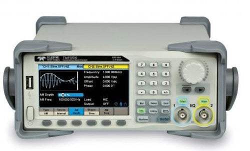
The Teledyne Test Tools T3AFG200, T3AFG350, and T3AFG500 are dual-channel function/arbitrary waveform generators offering up to 500 MHz of bandwidth, a 2.4 GSa/s maximum sampling rate, and 16-bit vertical resolution. Proprietary Arbitrary and Pulse generation techniques (TrueArb and EasyPulse) address the weaknesses inherent in traditional DDS generators when producing arbitrary, square, and pulse waveforms, allowing the series to deliver high-fidelity, low-jitter signals across a wide range of complex applications.
A function/arbitrary waveform generator produces known, controllable stimulus signals — from standard sine, square, ramp, pulse, noise, and DC waveforms to fully user-defined arbitrary waveforms — so an engineer can drive a circuit under test and observe how it responds. The T3AFG series is built around debugging confidence: its low-jitter design generates waveforms with exceptional edge stability, and wide-bandwidth Gaussian noise can be added to other waveforms to simulate real-world conditions in which the signal carries a large degree of noise.
ValueTronics stocks and holds its own inventory in a 20,000 sq ft secure warehouse at 1675 Cambridge Drive in Elgin, Illinois.
Teledyne Test Tools is a brand and trademark of Teledyne LeCroy Inc., a test-and-measurement company founded in 1964. LeCroy Corporation became part of Teledyne Technologies in 2012, after which the business operated under the Teledyne LeCroy name.
The T3AFG series is a range of dual-channel function/arbitrary waveform generators offered in three bandwidth models — the T3AFG200 (200 MHz), T3AFG350 (350 MHz), and T3AFG500 (500 MHz). All three models share the same core architecture: two independent output channels, 20 Mpts of arbitrary memory per channel, a 2.4 GSa/s sample rate with 2x interpolation, and 16-bit vertical resolution.
Across the family, the proprietary TrueArb and EasyPulse techniques, the wide modulation suite, the built-in frequency counter, and the 4.3-inch touchscreen interface are common to every model. The primary distinction between models is maximum bandwidth and the frequency limits of the individual waveform types, detailed in the comparison table below.
Each model below links to its own dedicated product page with condition-matched pricing for the new configuration you select. Choose the bandwidth tier that matches your application, then review the specifications and availability on that model's page.
The models differ chiefly in maximum bandwidth: 200 MHz on the T3AFG200, 350 MHz on the T3AFG350, and 500 MHz on the T3AFG500. This maps directly to the sine-wave frequency range, which extends to 200 MHz, 350 MHz, and 500 MHz respectively. Square-wave output reaches 80 MHz on the T3AFG200 and 120 MHz on both the T3AFG350 and T3AFG500, while pulse output reaches 80 MHz on the T3AFG200 and 150 MHz on the T3AFG350 and T3AFG500.
Pulse and PRBS edge performance also varies: the T3AFG200 provides a minimum rise/fall time of 2 ns, while the T3AFG350 and T3AFG500 reach 1 ns. PRBS bit rate tops out at 160 Mbps on the T3AFG200 and 300 Mbps on the T3AFG350 and T3AFG500. Channel count (two), memory (20 Mpts/ch), sample rate (2.4 GSa/s), and 16-bit resolution are identical across all three. See the comparison table that follows for the per-model figures.
| Model | Bandwidth | Channels | Memory per Ch |
|---|---|---|---|
| T3AFG350 | 350 MHz | 2 | 20 Mpts |
| T3AFG200 | 200 MHz | 2 | 20 Mpts |
| T3AFG500 | 500 MHz | 2 | 20 Mpts |
Additional differences in specifications beyond the few shown above are not listed here — see each model's full specifications below.
| Specification | Value |
|---|---|
| Frequency Specification | |
| Waveform | Sine, Square, Ramp, Pulse, Noise, Arbitrary |
| Sine | 1 μHz – 350 MHz |
| Square | 1 μHz – 120 MHz |
| Pulse | 1 μHz – 150 MHz |
| Ramp/Triangular | 1 μHz – 5 MHz |
| Gaussian white noise | 350 MHz (-3 dB) |
| Arbitrary | 1 μHz – 50 MHz |
| Resolution | 1 μHz |
| Accuracy | 10-year aging +/- 3.5 ppm at 25 Degrees C |
| Sine Wave | |
| Harmonic Distortion (0 dBm), DC – 1 MHz | ≤ -65 dBc |
| Harmonic Distortion (0 dBm), 1 MHz – 60 MHz | ≤ -60 dBc |
| Harmonic Distortion (0 dBm), 60 MHz – 100 MHz | ≤ -50 dBc |
| Harmonic Distortion (0 dBm), 100 MHz – 200 MHz | ≤ -40 dBc |
| Harmonic Distortion (0 dBm), 200 MHz – 300 MHz | ≤ -30 dBc |
| Harmonic Distortion (0 dBm), > 300 MHz | ≤ -28 dBc |
| Total harmonic distortion | 0.075 %, 0 dBm, 10 Hz – 20 kHz |
| Spurious signal (non-harmonic), DC ≤ 350 MHz | ≤ -60 dBc |
| Spurious signal (non-harmonic), > 350 MHz | ≤ -55 dBc |
| Maximum Amplitude Output, ≤ 40 MHz | 10 Vpp at 50 Ω, 20 Vpp at HiZ |
| Maximum Amplitude Output, 40 MHz – 120 MHz | 5 Vpp at 50 Ω, 10 Vpp at HiZ |
| Maximum Amplitude Output, 120 MHz – 160 MHz | 2.5 Vpp at 50 Ω, 5 Vpp at HiZ |
| Maximum Amplitude Output, 160 MHz – 350 MHz | 1.5 Vpp at 50 Ω, 3 Vpp at HiZ |
| Maximum Amplitude Output, > 350 MHz | 640 mVpp at 50 Ω, 1.28 Vpp at HiZ |
| Minimum Amplitude Output | 1 mVpp at 50 Ω, 2 mVpp at HiZ, all ranges |
| Square Wave | |
| Rise/Fall Time (10 % – 90 %) | 2.4 ns (1 Vpp, 50 Ω Load) |
| Overshoot | 3 % (typical, 100 kHz, 1 Vpp, 50 Ω Load) |
| Duty Cycle | 10 % – 90 %, Limited by frequency setting |
| Jitter (rms) cycle to cycle | 100 ps, 1 Vpp, 50 Ω Load |
| Maximum Amplitude Output, ≤ 20 MHz | 10 Vpp at 50 Ω, 20 Vpp at HiZ |
| Maximum Amplitude Output, > 20 MHz | 5 Vpp at 50 Ω, 10 Vpp at HiZ |
| Pulse | |
| Pulse width (Accuracy +/- (0.01 % + 0.3 ns)) | 3.3 ns |
| Rise/Fall Time (10 % ~ 90 %, typical) | 1 ns – 75 s |
| Pulse Width Adjustment Resolution | 100 ps |
| Duty Cycle | 0.001% ~ 99.999 %, 0.001% Resolution, Limited by frequency setting |
| Overshoot | 3 % (typical, 100 kHz, 1 Vpp, 50 Ω Load, 2 ns edge) |
| Jitter (rms, cycle to cycle) | 100 ps, 1 Vpp, 50 Ω Load |
| Maximum Amplitude Output (≥ 10 ns width, 2 ns edge), ≤ 20 MHz | 10 Vpp at 50 Ω, 20 Vpp at HiZ |
| Maximum Amplitude Output, 20 MHz – 120 MHz | 5 Vpp at 50 Ω, 10 Vpp at HiZ |
| Maximum Amplitude Output, > 120 MHz | 2.5 Vpp at 50 Ω, 5 Vpp at HiZ |
| Ramp/Triangle Wave | |
| Linearity | ≤ 1% of Vpp (typical, 1 kHz, 1 Vpp, 50 % symmetry) |
| Symmetry | 0 % – 100 % |
| Maximum Amplitude Output | 10 Vpp at 50 Ω, 20 Vpp at HiZ |
| Harmonic Output | |
| Order | 10 Maximum |
| Type | Even, Odd, All |
| Arbitrary Wave | |
| Waveform length | 2 – 20 M points |
| Vertical resolution | 16 bits |
| Sample rate | 300 MSa/s Arb Mode, 1.2 GSa/s DDS Mode |
| Min. Rise/Fall Time | 2.6 ns, 10 % – 90 %, 1 Vpp step signal, DDS mode |
| Jitter (rms), cycle to cycle | 100 ps, 1 Vpp, 50 Ω Load, TrueArb Mode |
| Frequency Setting Range | 1 μHz – 50 MHz |
| Maximum Amplitude Output, ≤ 20 MHz | 10 Vpp at 50 Ω, 20 Vpp at HiZ |
| Maximum Amplitude Output, > 20 MHz | 5 Vpp at 50 Ω, 10 Vpp at HiZ |
| PRBS | |
| Bit Rate | 1 μbps – 300 Mbps |
| Rise/Fall Time | 1 ns – 1 μs |
| Sequence Length | 2m-1, m = 3, 4, 5, ..., 32 |
| Maximum Amplitude Output, ≤ 40 Mbps | 10 Vpp at 50 Ω, 20 Vpp at HiZ |
| Maximum Amplitude Output, 40 Mbps – 240 Mbps | 5 Vpp at 50 Ω, 10 Vpp at HiZ |
| Maximum Amplitude Output, > 240 Mbps | 2.5 Vpp at 50 Ω, 5 Vpp at HiZ |
| Noise Characteristics | |
| -3 dB bandwidth | Bandwidth of the waveform generator |
| Bandwidth Setting Range | 1 mHz – Bandwidth of the waveform generator |
| Amplitude Output Range | 1 mVrms – 542 mVrms at 50 Ω, 2 mVrms – 1.084 Vrms at HiZ (Mean = 0, BW Limit = Off) |
| DC Characteristics | |
| Range | -10 V to +10 V HiZ Load, -5 V to +5 V 50 Ω Load |
| Accuracy | +/- (1% + 2 mV) HiZ Load |
| IQ Signal Generator (Option T3AFG-IQ) | |
| Maximum Carrier Frequency | 350 MHz |
| Symbol Rate | 250 Symbols/s – 37.5 MSymbols/s |
| Vertical Resolution | 16 Bits |
| Output Range | 1 mVrms – 0.5 Vrms, 50 Ω Load (√I2 + Q2) |
| Modulation Type | 2ASK, 4ASK, 8ASK, BPSK, QPSK, 8PSK, DBPSK, DQPSK, D8PSK, 8QAM, 16QAM, 32QAM, 64QAM, 128QAM, 256QAM, 2FSK, 4FSK, 8FSK, 16FSK, MSK, MultiTone, Custom (Supported by EasyIQ software) |
| Pattern | PN7, PN9, PN15, PN23, User file, Custom (Supported by EasyIQ software) |
| General Output Characteristics | |
| Accuracy | +/- (1% + 1 mVpp) 10 kHz sine wave, 0 V offset |
| Amplitude Flatness | +/- 0.3 dB, 50 Ω load, 0.5 Vpp (reference 1 MHz Sine wave) |
| Output impedance | 50 Ω +/- 0.5 Ω at 100 kHz Sine wave |
| Output current | +/- 200 mA |
| Channel to channel Crosstalk | -60 dBc, Sine, 50 Ω load |
| Current Limit Threshold | +/- 200 mA |
Important: The optional T3AFG-IQ IQ Signal Generation function requires the EasyIQ PC software to generate IQ waveforms.
This is a brand-new, factory-sealed unit, supplied exactly as it arrives from the manufacturer and backed by the full manufacturer warranty. For the exact configuration, available options, included accessories, or current lead time for your application, our Test Architects can confirm the details before you order.
ValueTronics supplies both new and used test and measurement equipment. New units ship factory-sealed, exactly as received from the manufacturer; every used unit is inspected and functionally verified in-house at our 20,000 sq ft secure facility in Elgin, Illinois before it ships. Our Test Architects can help you select the condition, calibration, and configuration that fit your application.
Please review the Manufacturer's Data Sheet to verify published specifications. Feedback on this webpage is always welcome — please reach out to your Test Architect at any time for questions or concerns. Thank you, we truly appreciate you being our customer.
Model No
Teledyne
Condition
Factory New
Manufacturer
Teledyne Test Tools
Func_gen_freq
350 MHz
T3AFG-IQ
IQ Signal Generator Function Option

30+ Years in Business
Secure Payments
Sell Test Equipments
Knowledgeable Staff
On-site Lab
30+ Years in Business
Secure Payments
Sell Test Equipments
Knowledgeable Staff
On-site Lab
Request A Quote
 Chat Live
 Contact Us
 sales@valuetronics.com