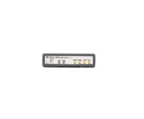
The Keysight N4877A is a clock data recovery and 1:2 demultiplexer instrument operating continuously from 50 Mb/s to 32 Gb/s. The instrument recovers a clock signal from incoming serial data streams and simultaneously demultiplexes those streams into two lower-rate parallel outputs, providing the synchronization and rate adaptation needed for receiver bit-error-ratio testing and transmitter waveform analysis at high-speed digital data rates.
Per the datasheet, the N4877A supports receiver tolerance testing with the J-BERT M8020A and J-BERT N4903B BERT platforms, transmitter characterization with sampling oscilloscopes equipped with precision time base modules, clock recovery and clean-up for clockless devices, and synchronization for emerging standards including 100 GbE, 32G Fibre Channel, CEI, InfiniBand, USB 3.0, SATA, SAS, SD UHS-II, and PCIe (including the 16 GT/s generation). The instrument is also positioned for PLL bandwidth and jitter transfer measurements when paired with the 86100DU-400 software and a precision jitter source.
ValueTronics has supplied professional T&M instruments since 1992 from our 20,000 sq ft secure warehouse at 1675 Cambridge Drive in Elgin, Illinois. Unlike drop-shippers or pass-through brokers, every {{CONDITION}} N4877A in our inventory is physically held, inspected, and prepared by our in-house technicians before it ships. That on-site control means we can verify performance against the published Keysight specifications, document the unit's actual condition rather than relying on a previous owner's description, and stand behind every transaction with direct accountability.
Keysight Technologies is the direct successor to Hewlett-Packard's test and measurement business. HP spun off its T&M division as Agilent Technologies in 1999, and in 2014 Agilent further split, with the electronic measurement business becoming Keysight Technologies. Instruments designed under Agilent before 2014 — including many products in the high-speed digital test portfolio — continue under Keysight support and development.
The N4877A is the core electrical clock data recovery and demultiplexer product within Keysight's broader CDR portfolio described in this datasheet. The same datasheet also defines two optical configurations built around the N4877A: the N1075A optical pick-off/converter, which adds an optical coupler and O/E converter front end, and the N1070A optical clock recovery solution, which bundles the N4877A with the N1075A as a complete optical CDR system.
Across the family, the N4877A provides the underlying clock recovery and demultiplexing engine. The optical variants extend that engine into the optical domain by adding wavelength-specific coupling and O/E conversion stages ahead of the N4877A's electrical data inputs. Data rate ranges, optical wavelengths, and split ratios differ between the multimode/single-mode (M14) and single-mode-only (S32) optical configurations.
Each pre-owned model below is its own dedicated product page with condition-matched pricing, accessory listings, and availability. Selecting the right configuration depends on whether your application is purely electrical (N4877A), requires optical signal handling (N1075A or N1070A), and on the maximum data rate and fiber type you need to support.
The N4877A specifically targets electrical CDR and 1:2 demultiplexing applications. Its 2.4 mm data inputs accept differential or single-ended AC-coupled electrical signals, and its three output paths — recovered clock, auxiliary clock, and dual demultiplexed data — are designed to drive BERT error detectors, sampling oscilloscope triggers, and precision time base reference inputs respectively. The instrument's option structure (Option 232 for 32 Gb/s, Option 216 for 16.5 Gb/s) lets the buyer match the rate range to the target standard without paying for unused capability.
The N4877A is the electrical-only base instrument. The N1075A-M14 adds a dual-path optical pick-off (multimode 30/70 split, single-mode 50/50 split) with an O/E converter rated DC-coupled to greater than 16 Gb/s, supporting 830–1360 nm multimode and 1250–1650 nm single-mode wavelengths. The N1075A-S32 is single-mode only with a 50/50 split, DC-coupled to 32 Gb/s, supporting 1300–1620 nm. Insertion loss is 4.5 dB on the supported paths; noise equivalent power is 10 µW (M14) or 7.5 µW typical (S32).
The N1070A is the integrated optical clock recovery solution, configured at order time by selecting an N4877A option (216 or 232) paired with an N1075A option (M14 or S32) plus the corresponding N1027A-M14 or N1027A-S32 phase-matching cable kit. The N1070A is the right choice when accurate trigger-to-sample phase alignment is required for jitter analysis on optical signals using an 86100 DCA. See the comparison table that follows for the specific data rate, wavelength, and connector differences between configurations.
| Model | Type | Max Data Rate | Signal Type |
|---|---|---|---|
| N4877A | Electrical CDR + Demux 1:2 | 32 Gb/s (Opt 232) / 16.5 Gb/s (Opt 216) | Electrical |
| N1075A | Optical Pick-Off/Converter | 32 Gb/s (S32) / >16 Gb/s (M14) | Optical (single-mode and/or multimode) |
| N1070A | Bundled Optical CDR Solution (N4877A + N1075A) | 32 Gb/s (S32/232) / >16 Gb/s (M14/216) | Optical (single-mode and/or multimode) |
Additional differences in specifications beyond the few shown above are not listed here — see each model's full specifications below.
| N4877A Specifications | |
|---|---|
| Data Inputs | |
| Input range (Option 232) | Specified: 380 Mb/s to 28.4 Gb/s; Over programming range: 50 Mb/s to < 380 Mb/s and > 28.4 Gb/s to 32 Gb/s |
| Input range (Option 216) | Specified: 380 Mb/s to 16.5 Gb/s; Over programming range: 50 Mb/s to < 380 Mb/s |
| Connector | 2.4 mm (f) |
| Interface | Differential or single-ended, AC coupled, 50 Ω; unused input must be terminated with 50 Ω |
| Input voltage window / max amplitude | −2.2 V to 3.2 V / 2 Vpp, max |
| Input sensitivity | 25 mV single-ended or differential to gain lock, typical; 70 mV single-ended or differential for Demultiplexer @ BER 10-12, typical |
| Min. transition density | 20% |
| Recovered Clock Output | |
| Connector | SMA (f) |
| Interface | Single-ended, AC coupled, 50 Ω |
| Output voltage | 350 mVpp, typical |
| Output frequency | 16 GHz, max |
| Output dividers | User definable: 1 up to 16 Gb/s; 2, 4, 8, 16 over full data-rate range |
| Peaking | Up to 4 peaking settings |
| Tracking range (incl. SSC) | 0.5% deviation, typical |
| Clock output jitter | 400 fs RMS for data rates < 2.5 Gb/s, typical; 250 fs RMS for data rates ≥ 2.5 Gb/s, typical |
| Auxiliary Clock Output | |
| Connector | SMA (f) |
| Interface | Single-ended, AC coupled, 50 Ω |
| Output voltage | 800 mVpp, typical |
| Output frequency | 4 GHz to 8 GHz |
| Output jitter | < 100 fs RMS, typical |
| Data Out 1 & 2 | |
| Connector | SMA (f) |
| Interface | Single-ended, AC coupled, 50 Ω |
| Data output voltage | 350 mVpp, typical |
| Demultiplexing ratio | 1:2 |
| Data output jitter | 5 ps pp, typical (measured @ 14.2 Gb/s using a 1100 pattern) |
| Skew: recovered clock to demux data out | 644 ps, typical |
| Loop Bandwidth | |
| Max loop bandwidth | 50 Mb/s to 62.5 Mb/s: 93.8 kHz; >62.5 to 125 Mb/s: 187.5 kHz; >125 to 250 Mb/s: 375 kHz; >250 to 500 Mb/s: 750 kHz; >500 Mb/s to 1.0 Gb/s: 1.5 MHz; >1.0 to 2.0 Gb/s: 3.0 MHz; >2.0 to 4.0 Gb/s: 6.0 MHz; >4.0 to 8.0 Gb/s: 12.0 MHz; >8.0 to 32 Gb/s: 20.0 MHz |
| Min loop bandwidth | 50 Mb/s to 750 Mb/s: 15 kHz; >750 Mb/s to 32 Gb/s: (data rate)/(5000 b) |
| Rear Panel & Remote Control | |
| Connectors rear panel | USB; LAN; IEC power connector |
| Connectivity | USB 2.0, LAN, rear panel |
| Programming language | Command line programming interface, SCPI |
| Standalone user interface | Color, graphical user interface |
| System requirements | Operating system: Microsoft Windows XP SP3 (32 bit), or Vista SP2 (32 and 64 bit), or Windows 7 SP1 (32 and 64 bit); Microsoft .NET 2.0 SP2 |
| General Characteristics | |
| Power consumption | 100–240 V, ~50/60 Hz, 90 VA, max |
| Operating temperature | 10 to 40 °C |
| Storage temperature | −40 to 70 °C |
| Operating humidity | 95% relative humidity, non-condensing |
| Storage humidity | 50% relative humidity |
| Physical dimensions (W x H x D), bench top with bumper | 228 x 59 x 360 mm (9.0 x 2.3 x 14.2 in) |
| Rack mount without bumper | 1/2 x 19" width, 1U height: 213 x 44.5 x 360 mm (8.4 x 1.8 x 14.2 in) |
| Weight net | 2.9 kg (6.4 lb) |
| Weight shipping | 5.5 kg (12.1 lb) |
| Regulatory Standards | |
| Safety | IEC61010-1:2010, EN61010-1:2010, CAN/CSA-C22 No. 61010-04, UL 61010-1:2004 |
| EMC | IEC61326-1:2005, EN61326-1:2006 |
| Quality management | ISO 9004, ISO 14001 |
Please review the Manufacturer's Data Sheet to verify published specifications. Feedback on this webpage is always welcome — please reach out to your Test Architect at any time for questions or concerns. Thank you, we truly appreciate you being our customer.
Model No
Keysight
Condition
Used
Manufacturer
Agilent

30+ Years in Business
Secure Payments
Sell Test Equipments
Knowledgeable Staff
On-site Lab
30+ Years in Business
Secure Payments
Sell Test Equipments
Knowledgeable Staff
On-site Lab
Request A Quote
 Chat Live
 Contact Us
 sales@valuetronics.com