Chat Live
 Contact Us
 sales@valuetronics.com


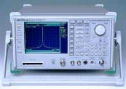
The MS2687B is a microwave spectrum analyzer covering a frequency range of 9 kHz to 30 GHz. Designed for the evaluation of Wireless LAN equipment and devices, it can measure up to 5th-order harmonics on 5-GHz Wireless LANs and is suited to OFDM signal analysis. With a maximum resolution bandwidth of 20 MHz, the instrument can measure the burst power of the wideband signals used by Wireless LANs, and when the optional measurement software is installed it can measure the modulation accuracy of each sub-carrier of an OFDM signal at high speed and high accuracy.
Across its documented applications, the MS2687B serves the R&D and manufacturing of wireless LAN equipment and devices, the installation and maintenance of radio stations, the maintenance of microwave entrance lines, and the development and production lines of various high-frequency and radio-frequency parts. Its 9 kHz to 30 GHz coverage spans the frequencies of various mobile communication systems and applications such as microwave entrance lines, and the range can be extended up to 110 GHz using an external mixer.
ValueTronics stocks and holds its own inventory in a 20,000 sq ft secure warehouse at 1675 Cambridge Drive, Elgin, Illinois. Every pre-owned unit is inspected and functionally verified in-house before it ships, while new units ship factory-sealed exactly as received from the manufacturer.
| Specification | Value |
|---|---|
| Frequency | |
| Frequency range | 9 kHz to 30 GHz (when using external mixer: to 110 GHz) |
| Frequency band (band 0) | 9 kHz to 3.2 GHz, mixer harmonics order N=1 |
| Frequency band (band 1–) | 3.15 to 6.3 GHz, N=1 |
| Frequency band (band 1+) | 6.2 to 7.9 GHz, N=1 |
| Frequency band (band 2+) | 7.8 to 15.3 GHz, N=2 |
| Frequency band (band 4+) | 15.2 to 30 GHz, N=4 |
| Pre-selector range | 3.15 to 30 GHz (band 1–, 1+, 2+, 4+) |
| Display frequency accuracy | ± (Display frequency x reference frequency accuracy + span x span accuracy + resolution bandwidth x 0.15 + 10 Hz x N Hz) |
| Frequency counter resolution | 1 Hz, 10 Hz, 100 Hz, 1 kHz |
| Frequency counter accuracy | ± (Display frequency x reference frequency accuracy + 2 x N Hz + 1 LSD) (at S/N 20 dB or more and RBW 3 MHz or less) |
| Frequency span setting range | 0 Hz, and 5 kHz to 30 GHz |
| Frequency span accuracy | ±1.0% (band 0, 1), ±2.5% (band 2, 4) |
| Resolution bandwidth (RBW) setting range | 300 Hz to 3 MHz (1, 3 sequence), 5 MHz, 10 MHz, 20 MHz (0 band) |
| RBW accuracy | ±20% (300 Hz to 10 MHz), ±40% (20 MHz) |
| RBW selectivity (60 dB: 3 dB) | ≤15 : 1 |
| Video bandwidth (VBW) | 1 Hz to 3 MHz (1, 3 sequence), Off |
| Signal purity, noise sideband | ≤–108 dBc/Hz (1 GHz, 10 kHz offset), ≤–120 dBc/Hz (1 GHz, 100 kHz offset) |
| Spurious resulting from local cause | ≤–65 dBc (at harmonic mixing order 1) |
| Reference oscillator frequency | 10 MHz |
| Reference oscillator start-up characteristics | ≤5 x 10⁻⁸ (after 10 minutes warm-up, with frequency after 24 hours warm-up referenced) |
| Reference oscillator aging rate | ≤2 x 10⁻⁸/day, ≤1 x 10⁻⁷/year |
| Reference oscillator temperature characteristics | ±5 x 10⁻⁸ (0 to 50˚C, with frequency at 25˚C referenced) |
| Amplitude | |
| Measurement range | Average noise level to +30 dBm |
| Maximum input level, continuous average power | +30 dBm (RF ATT: ≥10 dB) |
| Maximum input level, peak pulse input | +47 dBm (pulse width ≤1 µs, duty ratio ≤1%, RF ATT: ≥30 dB) |
| Maximum input level, DC voltage | 0 Vdc |
| Average noise level display (1 MHz to 2.5 GHz, band 0) | ≤–124 dBm + f [GHz] dB (RBW: 300 Hz, VBW: 1 Hz, RF ATT 0 dB, SAMPLE detection) |
| Average noise level display (2.5 to 3.2 GHz, band 0) | ≤–120 dBm + f [GHz] dB |
| Average noise level display (3.15 to 7.9 GHz, band 1) | ≤–115 dBm |
| Average noise level display (7.8 to 15.3 GHz, band 2) | ≤–113 dBm |
| Average noise level display (15.2 to 30.0 GHz, band 4) | ≤–103 dBm |
| Residual response (1 MHz to 3.2 GHz, band 0) | ≤–100 dBm (RF ATT 0 dB, input terminated at 50 Ω) |
| Residual response (3.15 to 7.8 GHz, band 1) | ≤–90 dBm |
| Setting range, log scale | –100 to +40 dBm or equivalent level |
| Setting range, linear scale | 2.24 µV to 22.4 V |
| Reference level accuracy | ±0.5 dB (–49.9 to 0 dBm), ±0.75 dB (+0.1 to +30 dBm, –69.9 to –50 dBm), ±1.5 dB (–80 to –70 dBm) |
| RBW switching uncertainty | ±0.3 dB (300 Hz to 5 MHz), ±0.5 dB (10, 20 MHz) |
| Input attenuator (RF ATT) setting range | 0 to 70 dB (10 dB step) |
| Input attenuator switching uncertainty | ±0.3 dB (10 to 50 dB), ±0.5 dB (50 to 70 dB) |
| Frequency response, relative flatness | ±1.0 dB (9 kHz to 3.2 GHz, band 0), ±1.5 dB (3.15 to 7.9 GHz, band 1), ±3.0 dB (7.8 to 15.3 GHz, band 2), ±4.0 dB (15.2 to 30 GHz, band 4) |
| Frequency response, absolute flatness | ±5.0 dB (9 kHz to 30 GHz) |
| Scale | 10 div (single scale); Log: 10, 5, 2, 1 dB/div; Linear: 10, 5, 2, 1%/div |
| Linearity, log scale | ±0.4 dB (0 to –20 dB, RBW ≤1 kHz), ±1.0 dB (0 to –70 dB, ≤1 kHz), ±1.2 dB (0 to –90 dB, ≤1 kHz) |
| Linearity, linear scale | 4% of reference level |
| Marker level resolution | Log scale: 0.01 dB, linear scale: 0.02% |
| 2nd harmonic distortion | ≤–60 dBc (10 to 200 MHz, Mixer input –30 dBm), ≤–70 dBc (0.2 to 1.6 GHz, Mixer input –30 dBm), ≤–90 dBc or lower than average noise level (1.6 to 15 GHz, Mixer input –10 dBm) |
| Two-signal third-order intermodulation distortion | ≤–70 dBc (10 to 100 MHz), ≤–85 dBc (0.1 to 3.2 GHz, band 0), ≤–80 dBc (3.15 to 7.9 GHz, band 1), ≤–75 dBc or lower than average noise level (7.8 to 15.3 GHz, band 2), ≤–75 dBc or lower than average noise level (15.2 to 30 GHz, band 4, Typical) |
| Image response | ≤–65 dBc (≤18 GHz), ≤–60 dBc (≤22 GHz), ≤–55 dBc (≤30 GHz) |
| Multiple response/spurious outside the band | ≤–60 dBc (≤22 GHz), ≤–55 dBc (≤30 GHz) |
| 1 dB gain compression | ≥0 dBm (≥100 MHz), ≥+3 dBm (≥500 MHz, band 0), ≥–5 dBm (≥3150 MHz, band 1, 2, and 4) |
| Frequency Sweep | |
| Sweep mode | Continuous, single |
| Sweep time setting range | 10 ms to 1000 s |
| Sweep time set resolution | 5 ms (5 ms to 1 s), top three digits (≥1 s) |
| Sweep time accuracy | ±3% |
| Trigger switch | Free run, triggered |
| Trigger source | Wide IF video, external (TTL), external (±10 V), line |
| Gate sweep, gate delay range | 0 to 65.5 ms (resolution: 1 µs) |
| Gate sweep, gate length range | 2 µs to 65.5 ms (resolution: 1 µs) |
| Gate end | Internal/external |
| Zone sweep | Sweeps the indicated range in the zone only |
| Tracking sweep | Sweeps following the peak point inside the zone marker |
| Time Sweep | |
| Sweep mode | Continuous, single |
| Sweep time setting range/resolution | 1 to 50 µs (1, 2, 5 sequence), 100 µs to 4.9 ms (100 µs resolution), 5.0 ms to 1 s (5 ms resolution), 1 to 1000 s (top three digits) |
| Sweep time accuracy | ±1% |
| Trigger switch | Free run, triggered |
| Trigger source | Wide IF video, video, external (TTL), external (±10 V), line |
| Trigger delay (pre-trigger) setting range | –time span to 0 s (resolution: time span/500 or 100 ns, whichever is larger) |
| Post-trigger setting range | 0 µs to 65.5 ms (resolution: 100 ns at sweep time ≤4.9 ms, 1 µs at ≥5 ms) |
| Number of data points | Selectable between 501 and 1001 |
| Detection mode | NORMAL, POSITIVE PEAK, NEGATIVE PEAK, SAMPLE, AVERAGE |
| Functions | |
| Display functions | TRACE A, TRACE B, TRACE A/BG, TRACE A/TIME |
| Trace calculation | A→B, B→A, A<=>B, A + B→A, A – B→A, A – B + DL→A |
| Storage functions | NORMAL, VIEW, MAX HOLD, MIN HOLD, AVERAGE, CUMULATIVE, OVER WRITE |
| Multi marker | 10 max. (highest 10, harmonics, manually set) |
| Noise power | dBm/Hz, dBm/CH, dBµV/√Hz |
| C/N | dBc/Hz, dBc/CH |
| Occupied bandwidth | power N% method, X-dB down method |
| Adjacent channel leakage power | REF: total power/reference level/in-band level method; channel designate display (3 channels x 2), graphic display |
| Average power within burst signal | average power in the designated range of time domain waveform |
Important: Maximum input level: +30 dBm continuous average power (RF ATT ≥ 10 dB); +47 dBm peak pulse input (pulse width ≤ 1 µs, duty ratio ≤ 1%, RF ATT ≥ 30 dB); DC voltage 0 Vdc.
Important: Optional measurement software is sold separately; it is installed in the mainframe via memory card and is required for high-speed modulation analysis. One set of measurement software is installable in up to three spectrum analyzers.
Important: The power meter function (Option 21/23/41/43/44) requires an external power sensor to be mounted on the front-panel connector. Power sensors (MA4601A, MA4701A, MA4703A, MA4705A) are optionally available and sold separately.
Important: Frequency coverage above 30 GHz (up to 110 GHz) requires an external mixer; external mixers (MA2741A through MA2746A) are optionally available and sold separately.
Important: Specified values are obtained after warming up the equipment for 30 minutes at a constant ambient temperature and then performing calibration. Typical values are given for reference and are not guaranteed.
Important: Options 47 and 48 (Rack mount IEC/JIS) eliminate the standard tilt handle when mounted.
This pre-owned unit is inspected and functionally verified in-house before it ships and is backed by our pre-owned warranty. To confirm its exact condition, firmware revision, installed options, or included accessories for your application before ordering, contact our Test Architects.
ValueTronics supplies both new and used test and measurement equipment. New units ship factory-sealed, exactly as received from the manufacturer; every used unit is inspected and functionally verified in-house at our 20,000 sq ft secure facility in Elgin, Illinois before it ships. Our Test Architects can help you select the condition, calibration, and configuration that fit your application.
Please review the Manufacturer's Data Sheet to verify published specifications. Feedback on this webpage is always welcome — please reach out to your Test Architect at any time for questions or concerns. Thank you, we truly appreciate you being our customer.
Model No
Anritsu
Condition
Pre-Owned
Manufacturer
Anritsu
Spec_ana_freq
9 kHz to 30 GHz


30+ Years in Business

Secure Payments

Sell Test Equipments

Knowledgeable Staff

On-site Lab
30+ Years in Business
Secure Payments
Sell Test Equipments
Knowledgeable Staff
On-site Lab
Request A Quote