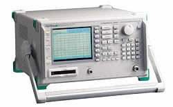
The Anritsu MS2667C is a portable spectrum analyzer covering 9 kHz to 30 GHz, designed for microwave and millimeter measurement applications. The instrument is positioned as a compact, lightweight platform that combines synthesized local oscillator stability, automatic calibration, and a 5.5-inch color TFT-LCD display in a 15 kg chassis. The standard configuration includes RS-232C and GPIB interfaces, a memory card interface supporting PCMCIA Rel. 2.0 cards up to 2 MB, and an external mixer input/output that extends frequency coverage into the millimeter range when paired with the MA2740A through MA2746A external mixers.
The MS2667C is intended for evaluation of radio equipment and microwave/millimeter signal characterization. Built-in measure functions handle frequency counting with 1 Hz resolution, C/N, channel power, adjacent channel power, occupied frequency bandwidth, burst average power measurement, and template pass/fail comparison in both time and frequency domains. The FM-demodulated waveform display function supports measurement of frequency deviation and frequency switching times for radio equipment and VCOs. With the external mixer ports, the instrument addresses applications above 30 GHz including measurements in the K, A, Q, U, V, E, and W bands up to 110 GHz.
Anritsu Corporation is a Japanese precision-measurement company headquartered in Atsugi, Kanagawa, with roots extending to 1895. In 1993, Anritsu acquired Wiltron Company, the U.S.-based RF and microwave instrument manufacturer, consolidating Wiltron's network analyzer and microwave product lines under the Anritsu brand. Today Anritsu operates as a single corporate brand for its full T&M portfolio, with no subsequent major restructuring or rebrand of the spectrum analyzer product line.
| Frequency | |
|---|---|
| Frequency range | 9 kHz to 30 GHz |
| Frequency band | Band 0: 0 to 3.2 GHz (n: 1), Band 1–: 3.1 to 6.5 GHz (n: 1), Band 1+: 6.4 to 8.1 GHz (n: 1), Band 2+: 8.0 to 15.3 GHz (n: 2), Band 3+: 15.2 to 22.4 GHz (n: 3), Band 4+: 22.3 to 30 GHz (n: 4) *n: harmonic order of the mixer |
| Pre-selector range | 3.1 to 30 GHz (band 1–, 1+, 2+, 3+, 4+) |
| Frequency setting resolution | (1 x n) Hz *n: harmonic order of the mixer |
| Frequency display accuracy | ± (display frequency x reference frequency accuracy + span x span accuracy) *Span: ≥ (10 x n) kHz (n: harmonic order of the mixer, after calibration) |
| Marker frequency display accuracy | Normal marker: Same as display frequency accuracy, Delta marker: Same as frequency span accuracy |
| Frequency counter | Resolution: 1 Hz, 10 Hz, 100 Hz, 1 kHz. Accuracy: Display frequency x reference frequency accuracy ± 1 LSD (at S/N: ≥ 20 dB) |
| Frequency span | Setting range: 0 Hz, 100 Hz to 30.0 GHz. Accuracy: ± 5% |
| Resolution bandwidth (RBW) (3 dB bandwidth) | Setting range: 1 kHz, 3 kHz, 10 kHz, 30 kHz, 100 kHz, 300 kHz, 1 MHz, 3 MHz (manually settable, or automatically settable according to frequency span). *Option 02 (30 Hz, 100 Hz, 300 Hz), Option 03 (10 Hz, 30 Hz, 100 Hz, 300 Hz) are added. Bandwidth accuracy: ± 20% (1 kHz to 1 MHz), ± 30% (3 MHz). Selectivity (60 dB : 3 dB): ≤ 15:1 |
| Video bandwidth (VBW) | 1 Hz to 3 MHz (1-3 sequence), OFF *Manually settable, or automatically settable according to RBW |
| Signal purity and stability | Noise sidebands: ≤ −95 dBc/Hz + 20 log n (1 MHz to 30 GHz, 10 kHz offset). Residual FM: ≤ 20 Hzp-p/0.1 s (1 GHz, span: 0 Hz). Frequency drift: ≤ 200 x n Hz/min (span: ≤ 10 kHz x n, sweep time: ≤ 100 s) *After 1-hour warm-up at constant ambient temperature; n: harmonic order of the mixer |
| Reference oscillator | Frequency: 10 MHz. Aging rate: 1 x 10⁻⁷/year, 2 x 10⁻⁸/day. Temperature characteristics: ± 5 x 10⁻⁸ (0° to 50°C, referenced to frequency at 25°C) |
| Amplitude | |
| Level measurement | Measurement range: Average noise level to +30 dBm. Maximum input level: +30 dBm (CW average power, RF ATT: ≥10 dB), ± 0 Vdc. Average noise level: ≤ −115 dBm (1 MHz to 1 GHz, band 0), ≤ −115 dBm + 1.5f [GHz] dB (1 to 3.1 GHz, band 0), ≤ −110 dBm (3.1 to 8.1 GHz, band 1), ≤ −102 dBm (8.0 to 15.3 GHz, band 2), ≤ −98 dBm (15.2 to 22.4 GHz, band 3), ≤ −91 dBm (22.3 to 30 GHz, band 4) *RBW: 1 kHz, VBW: 1 Hz, RF ATT: 0 dB. Residual response: ≤ −90 dBm (RF ATT: 0 dB, input: 50 Ω terminated, 1 MHz to 8.1 GHz) |
| Reference level | Setting range: Log scale: −100 to +30 dBm, Linear scale: 224 µV to 7.07 V. Unit: Log scale: dBm, dBµV, dBmV, V, dBµVemf, W; Linear scale: V. Reference level accuracy: ± 0.4 dB (−49.9 to 0 dBm), ± 0.75 dB (−69.9 to −50 dBm, 0.1 to +30 dBm), ± 1.5 dB (−80 to −70 dBm). RBW switching uncertainty: ± 0.3 dB (1 kHz to 1 MHz), ± 0.4 dB (3 MHz). Input attenuator (RF ATT): Setting range 0 to 70 dB (10 dB steps). Switching uncertainty: ± 0.3 dB (0 to 50 dB), ± 1.0 dB (0 to 70 dB) |
| Frequency response | Relative: ± 1.5 dB (9 to 100 kHz, band 0), ± 1.0 dB (100 kHz to 3.2 GHz, band 0), ± 1.5 dB (3.1 to 8.1 GHz, band 1), ± 3.0 dB (8 to 15.3 GHz, band 2), ± 4.0 dB (15.2 to 22.4 GHz, band 3), ± 4.0 dB (22.3 to 30 GHz, band 4). Absolute: ± 5.0 dB (9 kHz to 30 GHz, RF ATT: 10 dB, referenced to 100 MHz) |
| Waveform display | Scale (10 div): Log scale: 10, 5, 2, 1 dB/div; Linear scale: 10, 5, 2, 1%/div. Linearity (after calibration): Log scale: ± 0.4 dB (0 to −20 dB, RBW: ≤ 1 MHz), ± 1.0 dB (0 to −70 dB, RBW: ≤ 100 kHz), ± 1.5 dB (0 to −85 dB, RBW: ≤ 3 kHz), ± 2.5 dB (0 to −90 dB, RBW: ≤ 3 kHz); Linear scale: ± 4% (compared to reference level). Marker level resolution: Log scale: 0.01 dB, Linear scale: 0.02% of reference level |
| Spurious response | 2nd harmonic distortion: ≤ −60 dBc (10 to 200 MHz, band 0, mixer input: −30 dBm), ≤ −70 dBc (0.2 to 1.55 GHz, band 0, mixer input: −30 dBm), ≤ −90 dBc or noise level (1.55 to 15 GHz, band 1/2/3/4, mixer input: −10 dBm). Two signal 3rd order intermodulation distortion: ≤ −70 dBc (10 to 100 MHz), ≤ −80 dBc (0.1 to 8.1 GHz), −75 dBc or average noise level (8.1 to 26.5 GHz), ≤ −75 dBc or average noise level (typical, 26.5 to 30 GHz). Image response: ≤ −65 dBc (≤18 GHz), ≤ −60 dBc (≤ 22 GHz), ≤ −55 dBc (≤ 30 GHz). Multiple/out of band response: ≤ −60 dBc (≤ 22 GHz), ≤ −55 dBc (≤ 30 GHz) |
| 1 dB gain compression | ≥ −5 dBm (≥ 100 MHz, at mixer input) |
| Sweep | |
| Sweep time | Setting range: 20 ms to 1000 s (manually settable, or automatically settable according to span, RBW, and VBW). Accuracy: ± 15% (20 ms to 100 s), ± 25% (110 to 1000 s), ± 1% (time domain sweep: digital zero span mode) |
| Sweep mode | Continuous, single |
| Time domain sweep mode | Analog zero span, digital zero span |
| Zone sweep | Sweeps only in frequency range indicated by zone marker |
| Tracking sweep | Sweeps while tracing peak points within zone marker (zone sweep also possible) |
| Number of data points | 501 |
| Detection mode | NORMAL: Simultaneously displays max. and min. points between sample points; POS PEAK: Displays max. point between sample points; NEG PEAK: Displays min. point between sample points; SAMPLE: Displays momentary value at sample points. Detection mode switching uncertainty: ± 0.5 dB (at reference level) |
| Functions | |
| Display | Color TFT-LCD, Size: 5.5", Number of colors: 17 (RGB, each 64-scale settable), Intensity adjustment: 5 steps settable |
| Display functions | Trace A: Displays frequency spectrum. Trace B: Displays frequency spectrum. Trace Time: Displays time domain waveform at center frequency. Trace A/B: Displays Trace A and Trace B simultaneously. Trace A/BG: Displays frequency region to be observed (background) and object band (foreground) selected from background with zone marker simultaneously. Trace A/Time: Displays frequency spectrum, and time domain waveform at center frequency simultaneously. Trace move/calculation: A → B, B → A, A ↔ B, A + B → A, A − B → A, A − B + DL → A |
| Storage functions | NORMAL, VIEW, MAX HOLD, MIN HOLD, AVERAGE, CUMULATIVE, OVER WRITE |
| FM demodulation waveform display function | Demodulation range: 2, 5, 10, 20, 50, 100, 200 kHz/div. Accuracy: ± 5% of full scale. Demodulation frequency response: DC (50 Hz at AC-coupled) to 100 kHz (range: ≤20 kHz/div, VBW: off, at 3 dB bandwidth); DC (50 Hz at AC-coupled) to 500 kHz (range: ≥50 kHz/div, VBW: off, at 3 dB bandwidth) *RBW: ≥1 kHz to 3 MHz usable |
| Input connector | K-J, 50 Ω |
| Auxiliary signal input and output | IF OUTPUT: 10.69 MHz, BNC connector. VIDEO OUTPUT (Y): 0 to 0.5 V ± 0.1 V (typical, 10 dB/div); 0 to 0.4 V ± 0.1 V (typical, 10%/div), BNC connector. COMPOSITE OUTPUT: For NTSC, 1 Vp-p (75 Ω terminated), BNC connector. EXT REF INPUT: 10 MHz ± 10 Hz, −10 to +2 dBm (50 Ω terminated), BNC connector. REF BUFFERED OUTPUT: ≥0 dBm (50 Ω terminated), BNC connector. 1ST LOCAL OUTPUT: 4 to 7 GHz, ≥+8 dBm, 50 Ω, SMA-J connector |
| Signal search | AUTO TUNE, PEAK → CF, PEAK → REF, SCROLL |
| Zone marker | NORMAL, DELTA |
| Marker → | MARKER → CF, MARKER → REF, MARKER → CF STEP SIZE, Δ MARKER → SPAN, ZONE → SPAN |
| Peak search | PEAK, NEXT PEAK, NEXT RIGHT PEAK, NEXT LEFT PEAK, MIN DIP, NEXT DIP |
| Multimarker | Number of markers: 10 max. (HIGHEST 10, HARMONICS, MANUAL SET) |
| Measure | Noise power (dBm/Hz, dBm/ch), C/N (dBc/Hz, dBc/ch), occupied bandwidth (power N% method, X-dB down method), adjacent channel power, channel designate display: 2 channels x 2 graphic display, average power of burst signal, channel power (dBm, dBm/Hz), template comparison (upper/lower limits x each 2, time domain), MASK (upper/lower x each 2, frequency domain) |
| Save/recall | Saves setting conditions and waveform data to internal memory (max. 12) or memory card |
| Hard copy | Printer (HP dotmatrix, EPSON dotmatrix compatible models): Display data can be hard-copied via RS-232C, GPIB and Centronics (Option 10) interface. Plotter (HP-GL, GP-GL compatible models): Display data can be output via RS-232C, and GPIB interface. |
| PTA | Language: PTL (interpreter based on BASIC). Programming: Using external computer. Program memory: Memory card, upload/download to/from external computer. Programming capacity: 192 KB. Data processing: Directly accesses measurement data according to system variables, system subroutines, and system functions |
| RS-232C | Outputs data to printer and plotter. Control from external computer (excluding power switch) |
| GPIB | Meets IEEE488.2. Controlled by external computer (excluding power switch). Or controls external equipment with PTA. Interface function: SH1, AH1, T6, L4, SR1, RL1, PP0, DC1, DT1, C1, C2, C3, C4, C28 |
| Correction | Automatic correction of insertion loss of MA1621A Impedance Transformer. Correction accuracy (RF ATT: ≥10 dB): ± 2.5 dB (9 to 100 kHz), ± 1.5 dB (100 kHz to 2 GHz), ± 2.0 dB (2 to 3 GHz) *Typical value |
| Memory card interface | Functions: Saving/recalling measurement parameters/waveform data, uploading/downloading PTA programs. Applicable cards: SRAM, EPROM, Flash EPROM (Only SRAM writable; Card capacity: 2 MB max.). Connector: Meets the PCMCIA Rel. 2.0; 2 slots |
| External Mixer | |
| Frequency | Frequency range: 18 to 110 GHz. Frequency band configuration: Band K: 18 to 26.5 GHz (n: 4), Band A: 26.5 to 40 GHz (n: 6), Band Q: 33 to 50 GHz (n: 8), Band U: 40 to 60 GHz (n: 9), Band V: 50 to 75 GHz (n: 11), Band E: 60 to 90 GHz (n: 13), Band W: 75 to 110 GHz (n: 16). Span setting range: 0 Hz, (100 x n) Hz to each bandwidth |
| Amplitude (External mixer) | Mixer conversion loss setting range: 15 to 85 dB. Maximum input level: Depends on the external mixer used. Average noise level: Depends on the external mixer used. Reference level setting range: −100 dBm to (−25 to M) dBm *Log scale, M: mixer conversion loss. Frequency response: Depends on the external mixer used |
| Input/output (External mixer) | Suitable mixer: 2-port mixer only (local frequency: 4 to 7 GHz, IF frequency: 689.31 MHz). Display gain: 0 ± 2 dB (external mixer input: −10 dBm, when the mixer conversion loss is 15 dB) |
| Others | |
| EMC | EN61326: 1997/A2: 2001 (Class A); EN61000-3-2: 2000 (Class A); EN61326: 1997/A2: 2001 (Annex A) |
| LVD | EN61010-1: 2001 (Pollution Degree 2) |
| Conducted susceptibility | Meets the IEC801-4 (Level II) |
| Vibration | Meets the MIL-STD-810D |
Please review the Manufacturer's Data Sheet to verify published specifications. Feedback on this webpage is always welcome — please reach out to your Test Architect at any time for questions or concerns. Thank you, we truly appreciate you being our customer.
Model No
Anritsu
Condition
Used
Manufacturer
Anritsu
Frequency
30 GHz

30+ Years in Business
Secure Payments
Sell Test Equipments
Knowledgeable Staff
On-site Lab
30+ Years in Business
Secure Payments
Sell Test Equipments
Knowledgeable Staff
On-site Lab
Request A Quote
 Chat Live
 Contact Us
 sales@valuetronics.com