Chat Live
 Contact Us
 sales@valuetronics.com


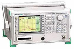
A spectrum analyzer displays the amplitude of input signals across a range of frequencies, letting an engineer see how signal power is distributed in the frequency domain. The Anritsu MS2665C is a compact, lightweight spectrum analyzer covering 9 kHz to 21.2 GHz, built around strong basic performance: a high C/N ratio, low distortion, and high frequency and level accuracies, combined with simple operation and a large selection of options to address a wide range of applications.
The MS2665C is positioned for the manufacturing and maintenance of radio equipment, with radio testing from RF through the microwave bands. At only 13 kg it can be moved easily from the bench to the field, suiting on-site maintenance and adjustment work that must be completed quickly. With its high-speed time domain sweep and trigger/gate options it also supports testing of TDMA-type digital mobile communication equipment, including antenna power, transient burst response, and transmission timing measurements.
ValueTronics stocks and holds its own inventory in a 20,000 sq ft secure warehouse at 1675 Cambridge Drive in Elgin, Illinois. Every used unit is inspected and functionally verified in-house before it ships, while new units ship factory-sealed exactly as received from the manufacturer. Holding the equipment ourselves means we can speak directly to what we have on hand and get the right instrument to you quickly.
Anritsu Corporation traces its roots to early-twentieth-century Japanese electrical manufacturing and adopted the Anritsu name in 1931. In 1990 Anritsu acquired the U.S. microwave instrument maker Wiltron Company, operating for a period as Anritsu Wiltron before consolidating fully under the Anritsu name in 1997.
| Specification | Value |
|---|---|
| Frequency | |
| Frequency range | 9 kHz to 21.2 GHz |
| Frequency band | Band 0: 0 to 3.2 GHz (n: 1), Band 1–: 2.92 to 6.5 GHz (n: 1), Band 1+: 6.4 to 8.1 GHz (n: 1), Band 2+: 8.0 to 15.3 GHz (n: 2), Band 3+: 15.2 to 21.2 GHz (n: 3) (n: harmonic order of the mixer) |
| Pre-selector range | 2.92 to 21.2 GHz (band 1–, 1+, 2+, 3+) |
| Frequency setting resolution | Frequency domain: (1 x n) Hz, Zero span: (100 x n) Hz |
| Frequency display accuracy | ± (display frequency x reference frequency accuracy + span x span accuracy + 100 Hz x n) (span: ≥10 kHz x n, after calibration) |
| Marker frequency display accuracy | Normal marker: Same as display frequency accuracy; Delta marker: Same as frequency span accuracy |
| Frequency counter | Resolution: 1 Hz, 10 Hz, 100 Hz, 1 kHz; Accuracy: Display frequency x reference frequency accuracy ± 1 LSD (at S/N: ≥20 dB) |
| Frequency span (setting range) | 0 Hz, 1 kHz to 21.3 GHz |
| Frequency span accuracy | ± 2.5% (span: ≥10 kHz x n), ± 5% (span: <10 kHz x n, Option 02 installed) |
| Resolution bandwidth (RBW, 3 dB) | 1 kHz, 3 kHz, 10 kHz, 30 kHz, 100 kHz, 300 kHz, 1 MHz, 3 MHz (Option 02 adds 30 Hz, 100 Hz, 300 Hz) |
| RBW bandwidth accuracy | ± 20% (1 kHz to 1 MHz), ± 30% (3 MHz) |
| RBW selectivity (60 dB : 3 dB) | ≤15:1 |
| Video bandwidth (VBW) | 1 Hz to 3 MHz (1-3 sequence), OFF |
| Noise sidebands | ≤–95 dBc/Hz + 20 log n (1 MHz to 21.2 GHz, 10 kHz offset) |
| Residual FM | ≤20 Hzp-p/0.1 s (1 GHz, span: 0 Hz) |
| Frequency drift | ≤200 x n Hz/min (span: ≤10 kHz x n, sweep time: ≤100 s) |
| Reference oscillator frequency | 10 MHz |
| Reference oscillator aging rate | 2 x 10⁻⁶/year (typical); Option 01: 1 x 10⁻⁷/year, 2 x 10⁻⁸/day |
| Reference oscillator temperature characteristics | 1 x 10⁻⁵ (typical, 0° to 50°C); Option 01: ± 5 x 10⁻⁸ (0° to 50°C, referenced to 25°C) |
| Amplitude | |
| Measurement range | Average noise level to +30 dBm |
| Maximum input level | +30 dBm (CW average power, RF ATT: ≥10 dB), ± 0 Vdc |
| Average noise level | ≤–115 dBm (1 MHz to 1 GHz, band 0), ≤–115 dBm + 1.5f [GHz] dB (1 to 3.1 GHz, band 0), ≤–110 dBm (2.92 to 8.1 GHz, band 1), ≤–102 dBm (8.0 to 15.3 GHz, band 2), ≤–98 dBm (15.2 to 21.2 GHz, band 3) (RBW: 1 kHz, VBW: 1 Hz, RF ATT: 0 dB) |
| Residual response | ≤–90 dBm (RF ATT: 0 dB, input: 50 Ω terminated, 1 MHz to 8.1 GHz) |
| Setting range | Log scale: –100 to +30 dBm; Linear scale: 224 µV to 7.07 V |
| Unit | Log scale: dBm, dBµV, dBmV, V, dBµVemf, W; Linear scale: V |
| Reference level accuracy | ± 0.4 dB (–49.9 to 0 dBm), ± 0.75 dB (–69.9 to -50 dBm, 0.1 to +30 dBm), ± 1.5 dB (–80 to –70 dBm) |
| RBW switching uncertainty | ± 0.3 dB (1 kHz to 1 MHz), ± 0.4 dB (3 MHz) |
| Input attenuator (RF ATT) setting range | 0 to 70 dB (10 dB steps) |
| Input attenuator switching uncertainty | ± 0.3 dB (0 to 50 dB), ± 1.0 dB (0 to 70 dB) |
| Frequency response (relative) | ± 1.5 dB (9 to 100 kHz, band 0), ± 1.0 dB (100 kHz to 3.2 GHz, band 0), ± 1.5 dB (2.92 to 8.1 GHz, band 1), ± 3.0 dB (8 to 15.3 GHz, band 2), ± 4.0 dB (15.2 to 21.2 GHz, band 3) |
| Frequency response (absolute) | ± 5.0 dB (9 kHz to 21.2 GHz, RF ATT: 10 dB, referenced to 100 MHz) |
| Scale (10 div) | Log scale: 10, 5, 2, 1 dB/div; Linear scale: 10, 5, 2, 1%/div |
| Linearity (after calibration) | Log scale: ± 0.4 dB (0 to –20 dB), ± 1.0 dB (0 to –70 dB), ± 1.5 dB (0 to –85 dB), ± 2.5 dB (0 to –90 dB); Linear scale: ± 4% (compared to reference level) |
| Marker level resolution | Log scale: 0.01 dB, Linear scale: 0.02% of reference level |
| Spurious response - 2nd harmonic distortion | ≤–60 dBc (10 to 200 MHz, band 0, mixer input: –30 dBm), ≤–70 dBc (0.2 to 1.55 GHz, band 0, mixer input: –30 dBm), ≤–100 dBc or noise level (1.46 to 10.6 GHz, band 1/2/3, mixer input: –10 dBm) |
| Spurious response - Two signal 3rd order intermodulation distortion | ≤–70 dBc (10 to 100 MHz), ≤–80 dBc (0.1 to 8.1 GHz), –75 dBc or noise level (8.1 to 21.2 GHz) (frequency difference of two signals: ≥50 kHz, mixer input: –30 dBm) |
| Image response | ≤–65 dBc (≤18 GHz), ≤–60 dBc (>18 GHz) |
| Multiple response | ≤–60 dBc |
| 1 dB gain compression | ≥–5 dBm (≥100 MHz, at mixer input) |
| Sweep | |
| Sweep time setting range | 20 ms to 1000 s (manually settable, or automatically settable according to span, RBW, and VBW) |
| Sweep time accuracy | ± 15% (20 ms to 100 s), ± 25% (110 to 1000 s), ± 1% (time domain sweep: digital zero span mode) |
| Sweep mode | Continuous, single |
| Time domain sweep mode | Analog zero span, digital zero span |
| Zone sweep | Sweeps only in frequency range indicated by zone marker |
| Tracking sweep | Sweeps while tracing peak points within zone marker (zone sweep also possible) |
| Number of data points | 501 |
| Detection mode | NORMAL, POS PEAK, NEG PEAK, SAMPLE; Detection mode switching uncertainty: ± 0.5 dB (at reference level) |
| Display | |
| Display | Color TFT-LCD, Size: 14 cm, Number of colors: 17 (RGB, each 64-scale settable), Intensity adjustment: 5 steps settable |
| Display functions | Trace A, Trace B, Trace Time, Trace A/B, Trace A/BG, Trace A/Time |
| Trace move/calculation | A →B, B →A, A ↔B, A + B →A, A – B →A, A – B + DL →A |
| Storage functions | NORMAL, VIEW, MAX HOLD, MIN HOLD, AVERAGE, CUMULATIVE, OVER WRITE |
| FM demodulation - demodulation range | 2, 5, 10, 20, 50, 100, 200 kHz/div |
| FM demodulation - accuracy | ± 5% of full scale (referenced to center frequency, DC-coupled. RBW: 3 MHz, VBW: 1 Hz, CW) |
| Input/Output | |
| Input connector | N-J, 50 Ω |
| IF OUTPUT | 10.69 MHz, BNC connector |
| VIDEO OUTPUT (Y) | 0 to 0.5 V ± 0.1 V (typical, from lower edge to upper edge at 10 dB/div); 0 to 0.4 V ± 0.1 V (typical, from lower edge to upper edge at 10%/div), BNC connector |
| COMPOSITE OUTPUT | For NTSC, 1 Vp-p (75 Ω terminated), BNC connector |
| EXT REF INPUT | 10 MHz ± 10 Hz, ≥0 dBm (50 Ω terminated), BNC connector |
| Functions | |
| Signal search | AUTO TUNE, PEAK → CF, PEAK →REF, SCROLL |
| Zone marker | NORMAL, DELTA |
| Marker → | MARKER →CF, MARKER →REF, MARKER →CF STEP SIZE, ∆MARKER →SPAN, ZONE →SPAN |
| Peak search | PEAK, NEXT PEAK, NEXT RIGHT PEAK, NEXT LEFT PEAK, MIN DIP, NEXT DIP |
| Multimarker | Number of markers: 10 max. (HIGHEST 10, HARMONICS, MANUAL SET) |
| Measure | Noise power (dBm/Hz, dBm/ch), C/N (dBc/Hz, dBc/ch), occupied bandwidth, adjacent channel power, average power of burst signal, channel power (dBm, dBm/Hz), template comparison, MASK |
| Save/recall | Save and recall setting conditions and waveform data to internal memory (max. 12) or memory card |
| PTA | Language: PTL (interpreter based on BASIC); Programming capacity: 192 KB |
| RS-232C | Outputs data to printer and plotter. Control from external computer (excluding power switch) |
| GPIB | Meets IEEE488.2. Interface function: SH1, AH1, T6, L4, SR1, RL1, PP0, DC1, DT1, C1, C2, C3, C4, C28 |
| Memory card interface | SRAM, EPROM, Flash EPROM (Only SRAM writable; Card capacity: 2 MB max.); Meets PCMCIA Rel. 2.0; 2 slots |
| Others | |
| EMC | EN61326: 1997/A1: 1998 (Class A); EN61000-3-2: 1995/A2: 1998 (Class A); EN61326: 1997/A1: 1998 (Annex A) |
| LVD | EN61010-1: 1993/A2: 1995 (Installation Category II, Pollution Degree 2) |
| Vibration | Meets the MIL-STD-810D |
Important: Maximum input level: +30 dBm (CW average power, RF ATT >=10 dB); maximum DC input: +/-0 V.
Important: RF connector accepts input signals at levels up to +30 dBm; maximum DC input: ± 0 V (± 0 Vdc).
Important: GPIB interface (standard) and Option 10 (Centronics interface) cannot be installed simultaneously.
Important: Option 04 (High-speed time domain sweep) must be used with Option 06 (Trigger/gate circuit).
Important: The J0805 DC block, MA2507A/MA8601A/MA8601J DC Block Adaptors, MP612A RF Fuse Holder and impedance transformers are listed as application parts and are not included with the standard MS2665C delivery; order separately as required for your measurement setup.
Usage tip: the built-in correction function automatically compensates the insertion loss of the Anritsu MA1621A 50 ohm to 75 ohm Impedance Transformer for 75 ohm measurements.
This pre-owned unit is inspected and functionally verified in-house before it ships and is backed by our pre-owned warranty. To confirm its exact condition, firmware revision, installed options, or included accessories for your application before ordering, contact our Test Architects.
ValueTronics supplies both new and used test and measurement equipment. New units ship factory-sealed, exactly as received from the manufacturer; every used unit is inspected and functionally verified in-house at our 20,000 sq ft secure facility in Elgin, Illinois before it ships. Our Test Architects can help you select the condition, calibration, and configuration that fit your application.
Please review the Manufacturer's Data Sheet to verify published specifications. Feedback on this webpage is always welcome — please reach out to your Test Architect at any time for questions or concerns. Thank you, we truly appreciate you being our customer.
Model No
Anritsu
Condition
Pre-Owned
Manufacturer
Anritsu
Spec_ana_freq
9 kHz to 21.2 GHz


30+ Years in Business

Secure Payments

Sell Test Equipments

Knowledgeable Staff

On-site Lab
30+ Years in Business
Secure Payments
Sell Test Equipments
Knowledgeable Staff
On-site Lab
Request A Quote