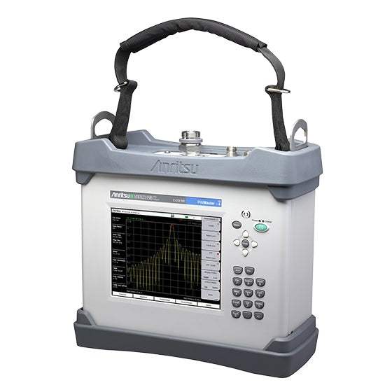
The Anritsu MW82119B PIM Master is a fully integrated Passive Intermodulation (PIM) analyzer that combines reverse-PIM measurement with an optional Site Master cable and antenna analyzer in a single battery-operated, field-portable instrument. Anritsu introduces it as the first fully integrated PIM analyzer plus cable and antenna analyzer suitable for commissioning and maintaining global wireless networks, letting operators characterize infrastructure quality from one unit.
Its purpose is to fully characterize wireless infrastructure quality by measuring Return Loss, VSWR, Cable Loss, Passive Intermodulation, Distance-to-Fault, and Distance-to-PIM. With Option 703 it adds 2-Port LTE 700 MHz PIM testing through a dedicated Port 2, so technicians can evaluate both the reflected PIM at an antenna line and the PIM passing through a two-port device.
ValueTronics stocks and holds its own test-equipment inventory in a 20,000 sq ft secure warehouse at 1675 Cambridge Drive, Elgin, Illinois. Pre-owned units are inspected and functionally verified in-house against the original manufacturer's specifications before shipment, while new units ship factory-sealed exactly as received.
| Specification | Value |
|---|---|
| PIM Master Connectors | |
| PIM Test Port | 7/16 DIN, female, 50 Ω |
| Port 2 Out | 4.3-10 (f) (option 703 only) |
| Port 2 Return | SMA (f) (option 703 only) |
| Dual USB Type A | 2x Type A (connect USB Flash Drive and USB Power Sensor) |
| USB Mini-B | 1x Mini-B (connect to PC for data transfer) |
| GPS | SMA, female (with GPS option only) |
| External Power | 2.1 mm x 5.5 mm barrel connector, 12 VDC to 15 VDC, < 5.0 A |
| PIM Test Port Damage Level | +10 dBm (10 mW) continuous (PIM Rx band); +35 dBm (3 W) continuous (PIM Tx band) |
| IM2/1900 MHz In Test Port | Type N, Female, 50 Ω (Option 902 and Option 600) |
| IM2/1900 MHz In Test Port Damage Level | +10 dBm (10 mW) continuous (IM2/1900 MHz Rx band) |
| VNA Test Port | Type N, female, 50 Ω (Option 331) |
| VNA Test Port Damage Level | 40 dBm continuous |
| Display | |
| Size | 213 mm (8.4 in) touch screen |
| Resolution | 800 x 600 |
| Pixel Defects | No more than five defective pixels (99.9989% good pixels) |
| Battery | |
| Type | Li-Ion |
| Battery Operation | 3.0 hours, typical |
| Charging Limits | While charging, battery must be 0 °C to +45 °C, Relative Humidity ≤80 % |
| Power | |
| AC/DC Adapter | Input: 100 VAC to 240 VAC, 50/60 Hz; Output: 12 VDC |
| Environmental (MIL-PRF-28800F Class 2) | |
| Operating Temperature Range | –10 ºC to 55 ºC |
| Storage Temperature Range | –51 ºC to 71 ºC |
| Maximum Relative Humidity | 95 % RH at 30 ºC, non-condensing |
| Vibration, Sinusoidal | 5 Hz to 55 Hz |
| Vibration, Random | 10 Hz to 500 Hz |
| Half Sine Shock | 30 gn |
| Altitude | 4600 meters, operating and non-operating |
| Explosive Atmosphere | MIL-PRF-28800F, Section 4.5.6.3; MIL-STD-810G, Method 511.5, Procedure 1 |
| Ingress Protection (IP) | IP54, IP67 when enclosed in optional transit case |
| ESD | |
| PIM Test Port Connector Center Pin | Withstands up to ±15 kV |
| VNA RF Out Connector Center Pin | Withstands up to ±15 kV |
| Size and Weight | |
| Size | 350 mm x 314 mm x 152 mm (13.8 in x 12.4 in x 6.0 in) |
| Weight | 9.2 kg to 12.4 kg (20 lb to 27 lb), varies by frequency option |
| PIM Analyzer — Measurement Ranges | |
| Test Method | Reverse (reflected) Passive Intermodulation (PIM) per IEC-62037-1 |
| Intermodulation Order | 3rd, 5th, and 7th order, when in receive band (user selectable) |
| RF Test Power | Two CW tones 20 dBm to 46 dBm, 0.1 dBm steps; Accuracy: ±0.5 dB (excluding uncertainty) |
| RF Test Frequency Accuracy | ±1.0 ppm at 23 ºC |
| RF Test Frequency Stability | ±1.0 ppm from –10 ºC to +55 ºC, typical |
| RF Test Frequency Aging | ±1.0 ppm/yr aging, typical |
| Residual PIM Performance | <–117 dBm, <–125 dBm typical (2x 43 dBm test tones); <–134 dBm, <–140 dBm typical (2x 20 dBm test tones) |
| 2-Port Residual PIM Performance | <–117 dBm, <–125 dBm typical (2x 43 dBm test tones); <–117 dBm, <–125 dBm typical (2x 20 dBm test tones) |
| PIM Measurement Range | –70 dBm to –140 dBm (Revision 1 instruments); –50 dBm to –140 dBm (Revision 2 instruments) |
| PIM Frequency Bands (by option) | |
| LTE 600 w/1900 MHz (Option 600) | Tx1: 617 MHz to 618 MHz, Tx2: 633 MHz to 652 MHz; Rx1: 663 MHz to 698 MHz, Rx2: 1867 MHz to 1888 MHz |
| LTE 700 (Option 700) | Tx1: 731 MHz to 734.5 MHz, Tx2: 746 MHz to 768 MHz; RxLower: 698 MHz to 717 MHz, RxUpper: 777 MHz to 806 MHz |
| APT 700 (Option 701) | Tx1: 758 MHz to 776 MHz, Tx2: 788 MHz to 803 MHz; RxLower: 710 MHz to 748 MHz, RxUpper: 825 MHz to 845 MHz |
| 2-Port LTE 700 (Option 703) | Tx1: 731 MHz to 734.5 MHz, Tx2: 746 MHz to 768 MHz; RxLower: 698 MHz to 717 MHz, RxUpper: 777 MHz to 806 MHz |
| LTE 800 (Option 800) | Tx1: 791 MHz to 795 MHz, Tx2: 811.5 MHz to 821 MHz; Rx: 832 MHz to 862 MHz |
| Cellular 850 (Option 850) | Tx1: 869 MHz to 871 MHz, Tx2: 881.5 MHz to 894 MHz; Rx: 824 MHz to 849 MHz |
| E-GSM 900 (Option 900) | Tx1: 925 MHz to 937.5 MHz, Tx2: 951.5 MHz to 960 MHz; Rx1: 880 MHz to 915 MHz |
| E-GSM 900 w/IM 2 (Option 902) | Tx1: 925 MHz to 937.5 MHz, Tx2: 951.5 MHz to 960 MHz; Rx1: 885 MHz to 915 MHz, Rx2: 1877 MHz to 1920 MHz |
| DCS 1800 (Option 180) | Tx1: 1805 MHz to 1837 MHz, Tx2: 1857.5 MHz to 1880 MHz; Rx: 1710 MHz to 1785 MHz |
| PCS/AWS (Option 194) | Tx1: 1930 MHz to 1945 MHz, Tx2: 1965 MHz to 1995 MHz, Tx3: 2110 MHz to 2155 MHz; Rx1: 1850 MHz to 1910 MHz (using Tx1 and Tx2), Rx2: 1710 MHz to 1755 MHz (using Tx1 and Tx3) |
| UMTS 2100 (Option 210) | Tx1: 2110 MHz to 2112.5 MHz, Tx2: 2130 MHz to 2170 MHz; RxLower: 1920 MHz to 1980 MHz, RxUpper: 2050 MHz to 2090 MHz |
| LTE 2600 (Option 260) | Tx1: 2620 MHz to 2630 MHz, Tx2: 2650 MHz to 2690 MHz; Rx: 2500 MHz to 2570 MHz |
| Cable and Antenna Analyzer (Option 331) | |
| Frequency Range | 2 MHz to 3 GHz |
| Frequency Accuracy | ±1.0 ppm at 23 ºC |
| Frequency Stability | ±1.0 ppm from –10 ºC to +55 ºC, typical |
| Frequency Aging | ±1.0 ppm/yr, typical |
| Output Power Level | –4 dBm, typical |
| Interference Immunity (On-Channel) | +17 dBm @ > 1.0 MHz from carrier frequency |
| Interference Immunity (On-Frequency) | 0 dBm within ± 10 kHz of the carrier frequency |
| Measurement Speed — Return Loss | 1.00 ms/data point, RF immunity low, typical |
| Measurement Speed — Distance-to-Fault | 1.25 ms/data point, RF immunity low, typical |
| Return Loss Measurement Range | 0 dB to 60 dB |
| Return Loss Resolution | 0.01 dB |
| VSWR Measurement Range | 1:1 to 65:1 |
| VSWR Resolution | 0.01 |
| Cable Loss Measurement Range | 0 dB to 30 dB |
| Cable Loss Resolution | 0.01 dB |
| Distance-to-Fault Vertical Range (Return Loss) | 0 dB to 60 dB |
| Distance-to-Fault Vertical Range (VSWR) | 1:1 to 65:1 |
| Distance-to-Fault Fault Resolution (meters) | (1.5 x 10^8 x vp) / F (vp = velocity propagation constant, F is F2–F1 in Hz) |
| Distance-to-Fault Horizontal Range (meters) | 0 to (Data Points–1) x Fault Resolution, to a maximum of 1500 meters (4921 ft) |
| 1-Port Phase Measurement Range | –180 º to +180 º |
| 1-Port Phase Resolution | 0.01 º |
| Smith Chart Resolution | 0.01, 50/75 Ω Selectable |
Important: PIM Test Port damage level: +10 dBm (10 mW) continuous in the PIM Rx band and +35 dBm (3 W) continuous in the PIM Tx band.
Important: The MW82119B PIM Master must be ordered with ONE frequency option (and only one).
Important: The High Accuracy Power Meter (Option 19) requires an external USB Power Sensor, which is sold separately (see the respective data sheet of each sensor for ordering information).
Important: The GPS Receiver (Option 31) requires a GPS antenna, which is sold separately.
Important: MW82119B-600 (Option 600) is not compliant with CE and RCM radiated emissions requirements.
Important: Calibration Components (50 Ω open/short/load standards) are not designed to withstand PIM test power levels and are suitable for cable and antenna analyzer measurements only.
Important: Recommended calibration cycle is 12 months.
Recommended pairing: for 2-Port LTE 700 PIM testing (Option 703), use the 2000-1991-R 2-Port PIM Loop Cable assembly, which includes the 2000-1989-R low PIM adapter and 2000-1990-R rigid cable per the recommended 2-port accessories.
This pre-owned unit is inspected and functionally verified in-house before it ships and is backed by our pre-owned warranty. To confirm its exact condition, firmware revision, installed options, or included accessories for your application before ordering, contact our Test Architects.
ValueTronics supplies both new and used test and measurement equipment. New units ship factory-sealed, exactly as received from the manufacturer; every used unit is inspected and functionally verified in-house at our 20,000 sq ft secure facility in Elgin, Illinois before it ships. Our Test Architects can help you select the condition, calibration, and configuration that fit your application.
Please review the Manufacturer's Data Sheet to verify published specifications. Feedback on this webpage is always welcome — please reach out to your Test Architect at any time for questions or concerns. Thank you, we truly appreciate you being our customer.
Model No
Anritsu
Condition
Pre-Owned
Manufacturer
Anritsu
Pim_ana_freq
2 MHz to 3 GHz
260
LTE 2600
31
GPS Receiver (requires GPS antenna)
331
Site Master™ Cable and Antenna Analyzer
850
Cellular 850 MHz

30+ Years in Business
Secure Payments
Sell Test Equipments
Knowledgeable Staff
On-site Lab
30+ Years in Business
Secure Payments
Sell Test Equipments
Knowledgeable Staff
On-site Lab
Request A Quote
 Chat Live
 Contact Us
 sales@valuetronics.com