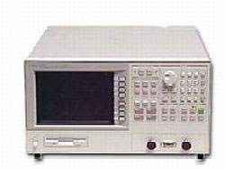
The Agilent 4291B is an RF Impedance/Material Analyzer covering 1 MHz to 1.8 GHz with 1 mHz frequency resolution. The instrument measures a comprehensive set of impedance parameters — |Z|, θz, |Y|, θy, R, X, G, B, Cp, Cs, Lp, Ls, Rp, Rs, D, Q, |Γ|, θy, Γx, Γy — at the tip of an APC-7 connector mounted on the test head connected to the mainframe. Specifications are warranted over 0°C to 40°C following a 30-minute warm-up.
The 4291B serves RF component characterization and material measurement applications. With Option 002 Material Measurement, the analyzer measures dielectric permittivity parameters (|εr|, εr', εr", tanδ) using the Agilent 16453A fixture and magnetic permeability parameters (|µr|, µr', µr", tanδ) using the Agilent 16454A fixture, both over a typical 1 MHz to 1 GHz range. High Temperature Test Head options (013 and 014) extend test head operating temperature from –55°C to +200°C for environmental characterization of RF components and materials.
ValueTronics International, LLC stocks, inspects, and tests instruments such as the Agilent 4291B at our 20,000 sq ft secure warehouse at 1675 Cambridge Drive, Elgin, Illinois. Our in-house technical team has handled RF impedance analyzers, material measurement systems, and the associated APC-7 calibration kits and test heads for decades, and every {{CONDITION}} unit is verified before it ships. Unlike drop-shippers or pass-through brokers, we physically have the instrument and can answer specific questions about its configuration, included accessories, and operational status before you commit to purchase.
Hewlett-Packard's test & measurement business was spun out as Agilent Technologies in 1999, and the electronic measurement portfolio was subsequently transferred to Keysight Technologies in 2014. Instruments originally produced under the Agilent brand, including the 4291B, are part of that lineage.
| Specification | Value |
|---|---|
| Measurement Parameters | |
| Impedance parameters | |Z|, θz, |Y|, θy, R, X, G, B, Cp, Cs, Lp, Ls, Rp, Rs, D, Q, |Γ|, θy, Γx, Γy |
| Frequency Characteristics | |
| Operating frequency | 1 MHz to 1.8 GHz |
| Frequency resolution | 1 mHz |
| Frequency reference accuracy @ 23±5°C | < ±10 ppm |
| Source Characteristics — OSC Level | |
| Voltage range @ 1 MHz ≤ Frequency ≤ 1 GHz (terminal open) | 0.2 mVrms to 1 Vrms |
| Voltage range @ 1 GHz < Frequency ≤ 1.8 GHz (terminal open) | 0.2 mVrms to 0.5 Vrms |
| Current range @ 1 MHz ≤ Frequency ≤ 1 GHz (terminal shorted) | 4 µArms to 20 mArms |
| Current range @ 1 GHz < Frequency ≤ 1.8 GHz (terminal shorted) | 4 µArms to 10 mArms |
| Power range @ 1 MHz ≤ Frequency ≤ 1 GHz (terminating with 50 Ω) | −67 dBm to 7 dBm |
| Power range @ 1 GHz < Frequency ≤ 1.8 GHz (terminating with 50 Ω) | −67 dBm to 1 dBm |
| AC power resolution | 0.1 dBm |
| Connector | APC-7 |
| Output impedance | 50 Ω (Nominal) |
| Sweep Characteristics | |
| Sweep parameters | Frequency, OSC level (voltage), DC bias voltage/current |
| Sweep setup | Start Stop, or Center Span |
| Frequency sweep type | Linear, Log, Zero-span, List |
| Other sweep types | Linear, Log, Zero-span |
| Sweep mode | Continuous, Single, Manual, Number of groups |
| Number of measurement points | 2 to 801 points |
| Averaging | Sweep average, Point average |
| Delay time | Point delay time, Sweep delay time |
| Measurement circuit mode | Series circuit mode, parallel circuit mode |
| Calibration/Compensation | |
| Calibration function | Open/Short/50 Ω calibration, Low loss calibration |
| Compensation function | Open/Short/Load compensation, Port extension, Electric length |
| Measurement Accuracy | |
| |Z|, |Y| Accuracy | ±(Ea + Eb) [%] |
| Ea @ 1 MHz ≤ Frequency ≤ 100 MHz | 0.6 |
| Ea @ 100 MHz < Frequency ≤ 500 MHz | 0.8 |
| Ea @ 500 MHz < Frequency ≤ 1000 MHz | 1.2 |
| Ea @ 1000 MHz < Frequency ≤ 1800 MHz | 2.0 |
| Display | |
| LCD type/size | Color TFT, 8.4 inch |
| Resolution | 640 × 480 |
| Effective Display Area | 160 mm × 115 mm (600 × 430 dots) |
| Number of display channels | 2 |
| Format | single, dual split or overwrite, graphic, and tabular |
| Traces for measurement | 1 trace/channel |
| Traces for memory | 16 traces/channel (maximum) |
| Data Storage | |
| Type | floppy disk drive, Volatile memory disk |
| Floppy disk capacity | 720 kB/1.44 MB |
| Volatile memory disk (flash backed) | 448 kB (maximum) |
| Disk format | LIF, DOS |
| GPIB | |
| Interface | IEEE 488.1-1987, IEC625 |
| Protocol | IEEE 488.2-1987 |
| Printer Parallel Port | |
| Interface | IEEE 1284 Centronics standard compliant |
| Printer control language | HP PCL3 Printer Control Language |
| Connector | D-sub (25-pin) |
| External I/O | |
| External reference input frequency | 10 MHz ±100 Hz (typically) |
| External reference input level | > −6 dBm (typically) |
| External reference input impedance | 50 Ω (nominal) |
| Internal reference output frequency | 10 MHz (nominal) |
| Internal reference output level | 2 dBm (typically) |
| External trigger input level | TTL Level |
| External trigger pulse width | > 2 µs (typically) |
| External monitor output connector | D-sub (15-pin HD) |
| External monitor display resolution | 640 × 480 VGA |
| I/O port | 4 bit in / 8 bit out port, TTL Level |
| Operation Conditions | |
| Operating temperature (Disk drive operating) | 10°C to 40°C |
| Operating temperature (Disk drive non-operating) | 0°C to 40°C |
| Operating humidity (Disk drive operating) | 15% to 80% RH (wet bulb < 29°C) |
| Operating humidity (Disk drive non-operating) | 15% to 95% RH (wet bulb < 29°C) |
| Operating altitude | 0 to 2,000 meters |
| Warm-up time | 30 minutes |
| Non-operation temperature | −20°C to 60°C |
| Non-operation humidity | 15% to 95% RH (wet bulb < 45°C) |
| Non-operation altitude | 0 to 4,572 meters |
| Compliance & Power | |
| EMC | Complies with CISPR 11 (1990) / EN 55011 (1991): Group 1, Class A; IEC 1000-3-2 (1995) / EN 61000-3-2 (1995); IEC 1000-3-3 (1994) / EN 61000-3-3 (1995); IEC 1000-4-2 (1995) / EN 50082-1 (1992): 4 kV CD, 8 kV AD; IEC 1000-4-2 (1995) / EN 50082-1 (1992): 3 V/m; IEC 1000-4-4 (1995) / EN 50082-1 (1992): 1 kV / Main, 0.5 kV / Signal Line |
| Safety | Complies with IEC 1010-1 (1990), Amendment 1 (1992) and Amendment 2 (1995); CSA-C22.2 No. 1010.1-92 |
| Power requirements | 90V to 132V, or 198V to 264V (automatically switched), 47 to 63 Hz, 300VA max |
| Physical | |
| Mainframe weight | 21.5 kg (SPC) |
| Test Station weight | 3.7 kg |
| Mainframe dimensions | 425 (W) × 235 (H) × 553 (D) mm |
| Test Station dimensions | 275 (W) × 95 (H) × 205 (D) mm |
Please review the Manufacturer's Data Sheet to verify published specifications. Feedback on this webpage is always welcome — please reach out to your Test Architect at any time for questions or concerns. Thank you, we truly appreciate you being our customer.
Model No
Agilent
Condition
Used
Manufacturer
Agilent

30+ Years in Business
Secure Payments
Sell Test Equipments
Knowledgeable Staff
On-site Lab
30+ Years in Business
Secure Payments
Sell Test Equipments
Knowledgeable Staff
On-site Lab
Request A Quote
 Chat Live
 Contact Us
 sales@valuetronics.com